If you spend any time at a speed shop or race track, you have inevitably heard someone mention “where their timing is set”. Some guys set timing while the engine idles, while others “adjust” things with the engine seemingly screaming past 6,000 rpm. Technically, both ways will allow the “tuner” to set some aspect of timing, but is only setting one aspect able to help the engine reach maximum power? Since we all know that the proper timing is one that lights the air/fuel mixture at the ideal point in the cycle to create maximum power, it is safe to assume that there is more to it.
Ignition is the point at which combustion actually occurs in an engine. This combustion is created when a high-voltage, low-amp charge is sent to the spark plug from—in this case, let’s say the distributor. This moment in time is measured in crankshaft degrees before the piston reaches top dead center (TDC). As a rule of thumb, engine builders will set the timing based on the Number 1 cylinder, and that cylinder (and all subsequent cylinders) will fire at a given point before TDC (BTDC). The first thing we should all understand is that making any assumptions when building and tuning an engine leads to problems.
Before we begin, we all need to understand that the time it takes for a consistent air/fuel mixture to combust does not change, even if engine speed increases. Therefore, the spark from the distributor needs to be advanced as engine rpm increases. This is done so that the combustion process occurs at the optimal time to efficiently push the piston down the cylinder. This need for advance is why distributors have an advance system built-in. On a street car, a vacuum-advance and a centrifugal-advance system are used. The vacuum advance increases timing as the vacuum created by the engine increases (idle and low-load conditions). As engine load or throttle position increases, the vacuum decreases, and so does vacuum advance timing. The centrifugal advance adds advance up until about 3,000 – 3,200 rpm, and is not attached to vacuum advance. Centrifugal advance keeps the combustion process in time with the piston location.
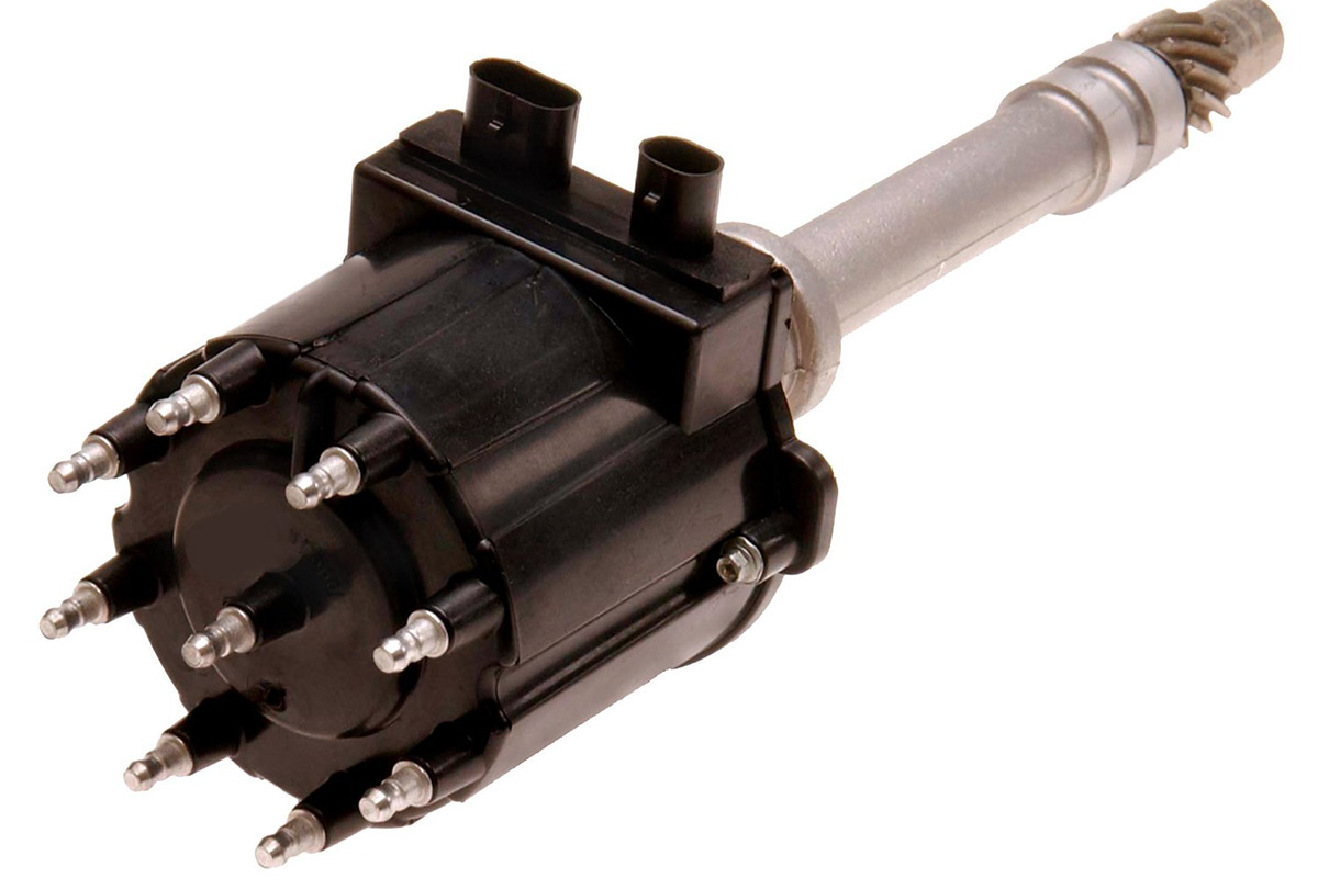
[caption id="attachment_14122" align="aligncenter" width="620"]

This shows the effects that rpm has on the mechanical advance. The left image shows the distributor with no advance while the image on the right shows full advance.[/caption]
On race cars, the engine spends very little time at low rpm, so many times the vacuum-advance system is eliminated. In general, cars with automatic transmissions with stock-type or even a slightly looser-than-stock torque converter respond well to more mechanical advance in the lower rpm range. Manual transmission-equipped vehicles and vehicles with torque converters that “stall” around 3,000 rpm and more, are not as sensitive to such changes because the engine is not usually loaded at the lower rpm.
What is meant by a timing advance-curve? Inside the distributor are advance springs and weights that are designed to advance the timing by centrifugal force as the engine speed increases. If advance is measured at small increments of engine rpm, the timing figures created by the weights and springs as they move outward during engine acceleration will define the advance curve when plotted on a graph. Factory advance curves are engineered to provide acceptable performance and emissions control. However, varying the curve from a factory stock setting will usually yield improved engine performance.
[caption id="attachment_14124" align="aligncenter" width="391"]

Stock distributor springs are usually too stiff for a performance application. This causes the advance curve to come in too slowly. All you need are the right springs and the right initial advance setting. You want your timing "all in" by about 3,000-3200 rpm. You can change the rate of advance by changing the centrifugal advance springs to lighter ones. These springs are easy to replace by hand or with needle nose pliers. Changing the springs will give you an advance curve that starts at about 1,000 rpm, and ends at around 3,000 – 3,200 rpm. It doesn't matter if the springs are not matched from side to side. You can install one heavy one and one light one.[/caption]
One way to get a quicker advance curve is by changing the centrifugal weights, and their springs. The weights pivot on pins that are attached to the distributor shaft, and the center plate is attached to the movable assembly that holds the rotor. The springs are connected between shaft posts and the rotor posts, and the springs try to hold the two weights inward, but when the engine is running, the centrifugal force generated by the rotation of the weights pull the weights outward, which advances the rotor--and therefore ignition timing--at the rate and amount dictated by the shape of the intersecting points of the weights and the center plate.
Adding heavier weights and retaining the stock advance springs will allow the curve to advance quicker than when using factory weights. Likewise, lighter springs and stock weights will incur the same result. However, very light springs can fatigue (stretch) quickly, and eventually, the weights might stick more outward, causing hard starting and poor performance.
The center plate also has an effect on both the curve and the maximum advance. Its shape defines the advance rate and the maximum allowable advance, and modifying the shape of the center plate is easy and yields significant results.
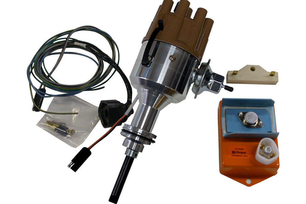
[caption id="attachment_14125" align="alignright" width="418"]

The springs in a Mopar distributor are under the breaker plate.[/caption]
A good rule of thumb is that the higher the engine’s compression ratio, the less total timing it can use before detonation occurs. Also, a higher octane fuel is required for the engine, to help control detonation. Low octane fuels ignite faster, thus require less timing advance. Conversely, high octane fuel can handle slightly more timing advance. Dyno testing has shown that most small blocks running Premium pump gas with 9.0:1 - 9.5:1 compression make peak horsepower with roughly 38-42 degrees of total advance. Engines with 9.5:1 - 10.5:1 typically require 35-38 degrees total. Finally, if running an engine with a compression ratio above 10.5:1, total advance should not go higher than 35 deg. total. When using power adders, the timing should be advanced accordingly.
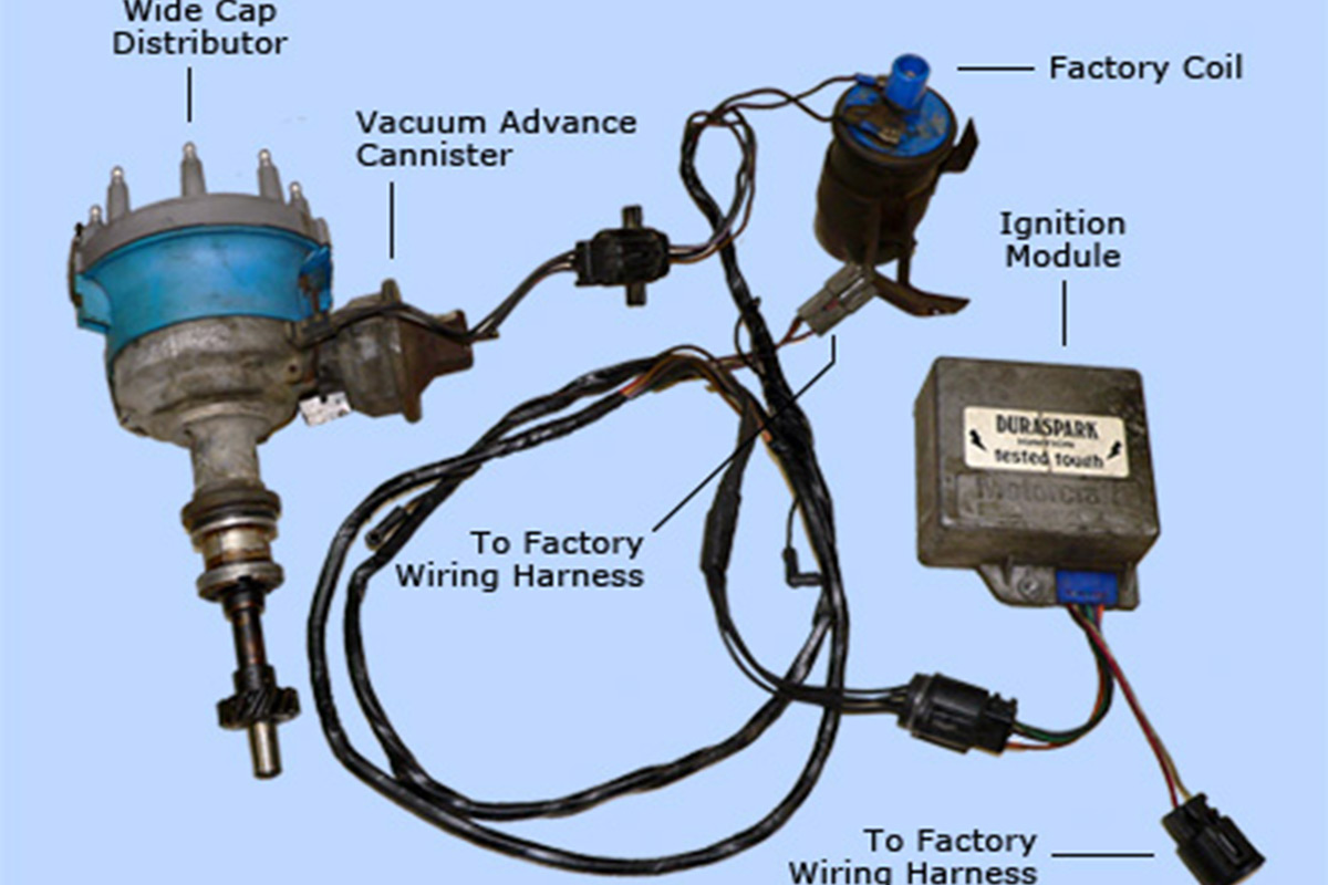
[caption id="attachment_14126" align="alignleft" width="400"]

The weights and springs in a Ford distributor are also under the breaker plate.[/caption]
To get the timing properly set, you will need either a timing light with a dial on the back of it, timing tape on your balancer or a balancer with degree marks. Set your initial timing to where the engine idles best. Using the timing light and tachometer, increase the engine rpm until the timing stops advancing. You should see total advance before 3,000 – 3,200 rpm.
The first thing to set when curving a distributor is to set your initial and total advance. Ideally, you want to keep the initial advance between 10 and 20 degrees while starting with the total advance in the ranges listed above for your compression ratio. What that means is, if you are shooting for 40 degrees of total timing, and your distributor allows 30 degrees of mechanical advance, that would require the initial timing to be set at 10 degrees.
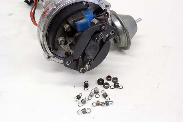
[caption id="attachment_14127" align="aligncenter" width="620"]

GM makes it easy to change the springs, as they are located directly under the rotor cap.[/caption]
The second step is to tune how fast that the distributor reaches total advance. This is controlled by the springs which try to keep the weights from moving. A stock distributor usually has springs that allow the mechanical timing to increase at a relatively slow rate. This means that the mechanical advance might not be fully advanced before 3,500 rpm. For performance driving, the best acceleration comes when total advance is achieved before 3,000 rpm. To adjust this rate of advance, you can replace the stock springs with springs that have a lighter tension. Aftermarket spring kits come with springs of varying tension, and you can mix and match the springs until you get the advance rpm you need. Using one heavy and one light spring isn't a problem.
[caption id="attachment_14128" align="alignleft" width="402"]

If the mechanical advance travels too far, limiting bushings need to be installed on the limiting pin. This pin is located under the advance mechanism on a GM distributor.[/caption]
Once you've set the initial and mechanical timing, and adjusted the curve, you should be very close to the optimum timing curve for wide-open throttle performance. At this point, you can use a timing light to confirm that the initial timing is where you set it, and then check the timing from idle to 3,500 rpm in 500 rpm increments. The curve should steadily increase only a few degrees at every 500 rpm, until it reaches the maximum 3,000 – 3,200 rpm. After 3,200 rpm, the timing should not go beyond the total advance.
What base and total timing is best? Although we gave some guidelines, each engine is different and might like a different timing setting.
Timing Terms
Initial: This is the most common adjustment that people associate with timing. At idle, with the vacuum advance hose disconnected and plugged at he carburetor, this is the timing that you see with the timing light on the timing marks. On a typical stock engine, you usually see around see 8-13 degrees.
Mechanical/Centrifugal: Most V-8 distributors contain an internal advance mechanism consisting of two weights, two springs, and a slotted 'reluctor' arm. There is also a stop tab for the arm. On GM HEI distributors these weights and springs are just under the rotor cap. In Ford and Mopar distributors, this assembly is not only under the rotor, but also the breaker plate. As the distributor shaft spins with increasing rpm, the centrifugal force acts on the weights, which forces them outwards against the tension of the springs. This movement rotates the shaft and plate, thus advancing the timing. The slotted arm under the weights controls how much the weights can move, while the springs control how fast the assembly reaches that limit.
[caption id="attachment_14129" align="aligncenter" width="638"]

On a Mopar distributor, you will need to shorten the slot. This is usually done by welding it.[/caption]
Total Advance: So far we have looked at initial and mechanical advance. Both of these combined gives total advance. If your initial timing is 10 degrees, and we visually verified that mechanical advance allows 24 degrees, your total timing, theoretically, is then initial plus mechanical (10 + 24+34). If we shine a timing light on the damper (with vacuum hose disconnected and plugged), at idle, we would see 10 degrees. But, when we increase the engine speed, we will see increasing advance, until the total centrifugal advance is reached, and we would see 34 degrees. When exactly the total advance occurs is of great importance when it comes to performance, and we discuss this in the section about "curving."
Most distributors include a vacuum advance mechanism, which consists of a diaphragm vacuum canister, an arm from the canister to the breaker plate, and a hose connected to an engine vacuum source. The purpose of the vacuum advance is to provide spark advance when the engine is not spinning fast enough to create the centrifugal advance talked about earlier. The vacuum advance is an engine-load dependent advance. During conditions when there is high engine vacuum, the vacuum applied to the diaphragm in the canister, will cause a pull effect on the arm, which moves the breaker plate and results in a timing advance. During full throttle conditions there isvery little engine vacuum, and the vacuum advance does not contribute to total advance.
[caption id="attachment_14130" align="aligncenter" width="620"]
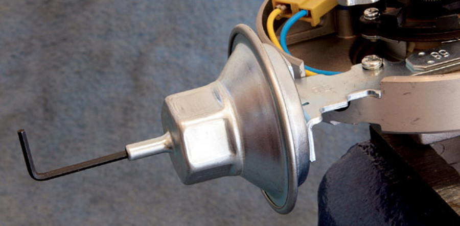
Adjusting the vacuum advance is nearly impossible, unless you install an adjustable unit—which is a great idea by the way. Stock canisters typically provide 22-24 degrees of advance. This is too much once you have recurved the centrifugal and initial advance. Your engine needs around 12 degrees total vacuum advance if you run without a functional EGR system, 16 degrees if you run with a functional EGR system. Regardless, you want it to come in between about 5 and 15 inches of manifold vacuum.[/caption]
Vacuum advance is tricky to tune because there is no direct measurement available like when dealing with total. In fact, the reason you must measure initial and total timing with the vacuum advance disconnected is because when the engine is in neutral there no load, the vacuum is high, and if the hose were connected you could see as high as 60 degrees advance and think something is wrong. The only way to properly tune the vacuum advance is by driving the car. And this should only be done after the initial and total timing are adjusted.
Vacuum advance was developed to optimize fuel economy and reduce emissions. While it is not a bad thing to have on a car that sees a lot of street driving, many aftermarket performance distributors do not even come with a vacuum advance. The reason is because race cars do not spend much time at part throttle.
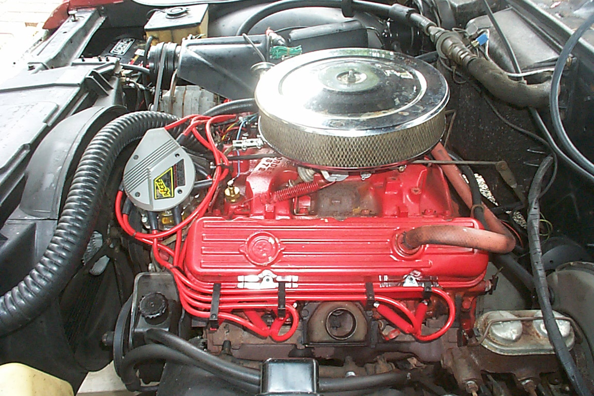
[caption id="attachment_14123" align="aligncenter" width="638"]

Finally, to even think about adjusting the timing advance in your distributor, you will need either a timing light with a dial on the back of it, timing tape on your damper/balancer, or a damper/balancer with degree marks.[/caption]
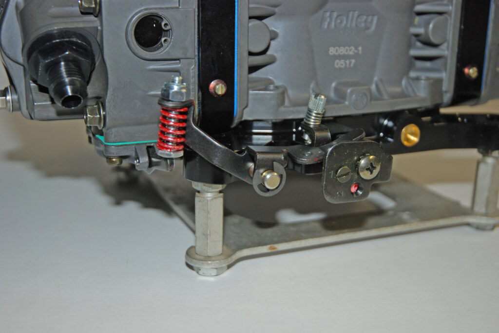
When looking at the vacuum advance, there should be a vacuum line connecting the carburetor to the vacuum canister. There are two types of vacuum sources that you need to be aware of; manifold and timed/ported vacuum. Manifold vacuum is a direct connection to the intake manifold, and if the hose is connected to this port, you will have full vacuum in the line at idle. The timed/ported vacuum only yields a vacuum when the engine reaches a certain rpm. At idle, the timed vacuum port will have no vacuum. Most carburetors have both ports. On Holley's the timed is above the throttle blades, and the manifold is near the base. On Carter/Edelbrock carburetors, the timed port is on the passenger side and the manifold is on the driver's side. The easiest way to confirm what port you have is to hook up a vacuum a gauge and check for vacuum at idle. The preferred vacuum source is the timed source. This way there is no effect on the initial timing setting.
Keep Reading:
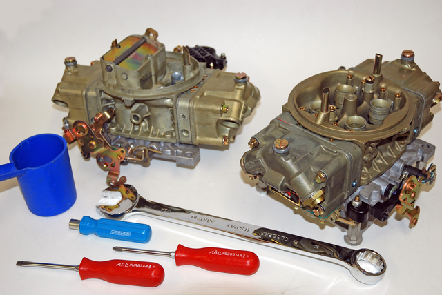
How and Why to Adjust a Holley Carburetor Accelerator Pump


![[Gallery] 3rd. Annual Father's Day Classic Car Show](https://www.racingjunk.com/news/wp-content/uploads/2026/07/Calistoga-2026-18-scaled-e1783026475349-376x206.jpg)


![[Gallery] Blackhawk Museum Stop Over](https://www.racingjunk.com/news/wp-content/uploads/2026/06/DSC_0918-e1782449621944-376x206.jpg)
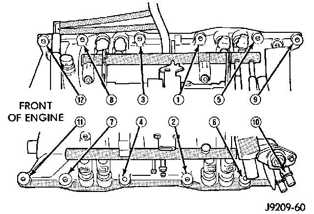
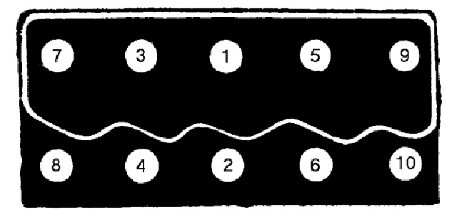
 Different backlash pattern markings—correct and incorrect.
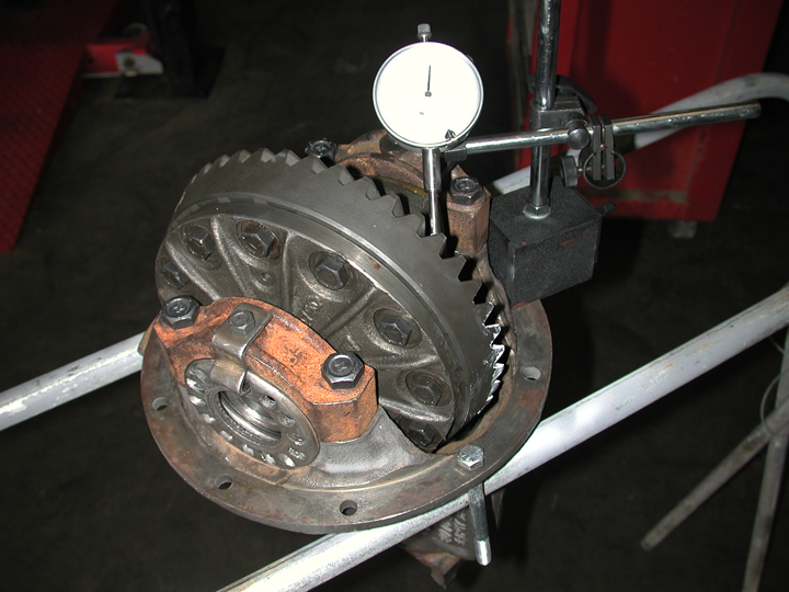 Setting backlash is done using a dial indicator to measure the free movement of the ring gear.
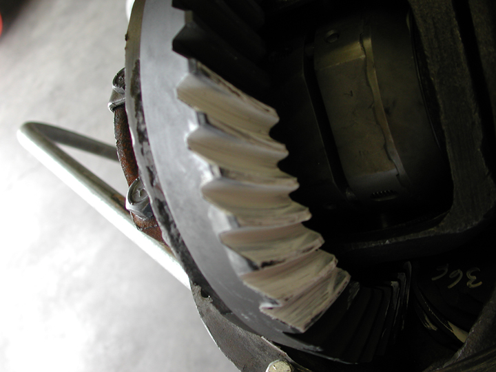 A typical set of gears comes with a marking compound. This compound is used to show what the pattern actually is on the ring gear while adjusting the backlash. In this image, the pinion depth is too deep (too far into the housing) and needs more shims. This is shown by the wear pattern on the inside of the teeth.
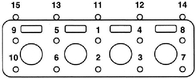
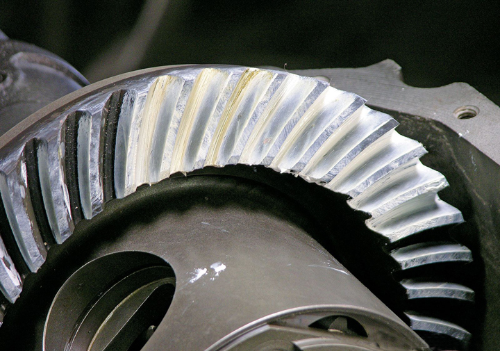 The right pattern will show that the gears are fully meshing but are not too tight. Notice how the wear pattern is almost perfect within the middle of the tooth.

 Engine cranks over, but will not start when cold: Check the fuel filter.[/caption]
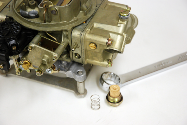 Engine starts hard when hot: Check the fuel pump.[/caption]
 Engine starts and stalls: Check the float level.[/caption]
 Engine idles rough and stalls: Correct idle speed setting.[/caption]
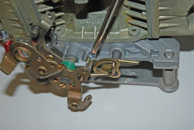 Engine runs uneven or surges: Check for vacuum leaks.[/caption]
 Engine hesitates on acceleration: Check the accelerator pump system.[/caption]
 No power on heavy acceleration or at high speed: Check the jets.[/caption]
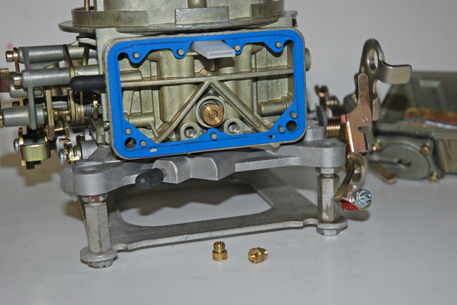 Poor fuel economy: Check the power valves.[/caption]
 Engine backfires: Clean or replace spark plugs.[/caption]
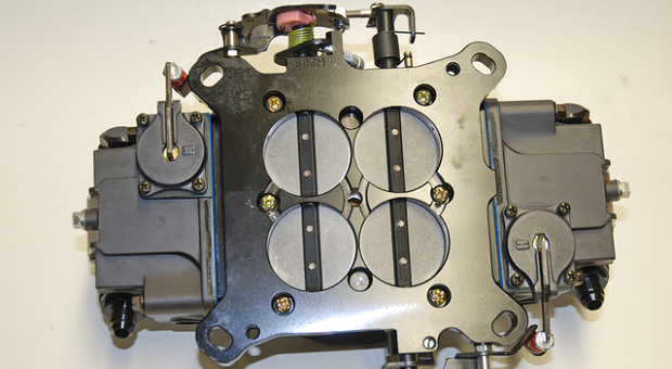
 Secondaries don’t open: Sticking throttle plates.[/caption]
 Image courtesy pakwheels.com[/caption]
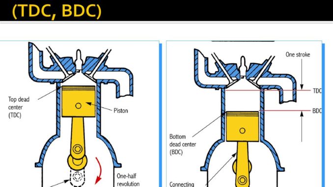 Image courtesy Danny's Engine Portal[/caption]

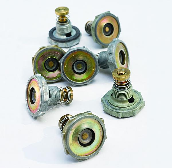
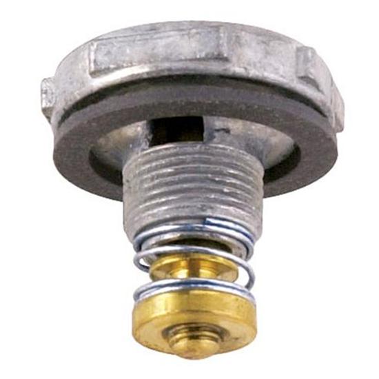 Engine vacuum is what actually operates a Holley power valve. The spring that is part of the power valve is the resistance to the diaphragm that only allows it to open at a certain vacuum reading. Spring pressure is what changes the actual operating range of the power valve.[/caption]
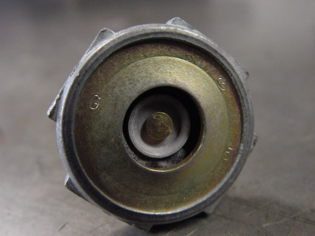 Knowing what power valve you have is as easy as reading numbers. The face of this power valve has the numbers 6 and 5 on it. That means that this valve opens at 6.5 inches of vacuum.[/caption]
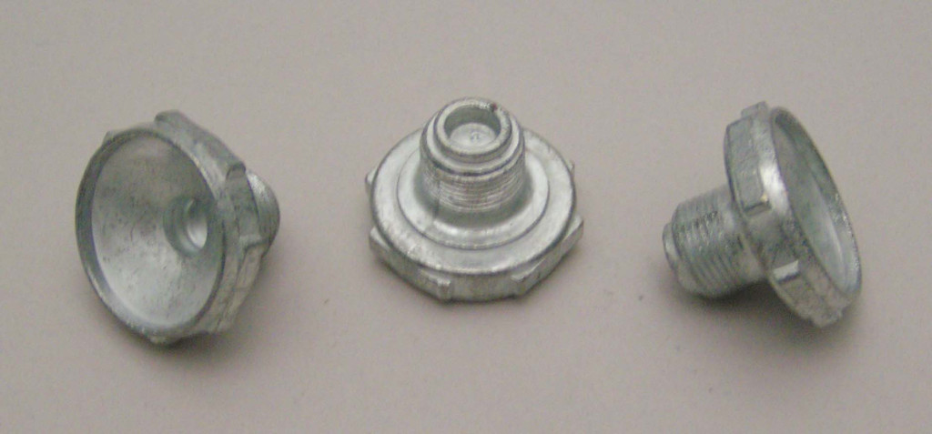 In a race-only application, some will remove the power valve from the carburetor, and install plugs. If the engine is only ever run at wide-open throttle, this is not a problem, but any street driving and your fuel economy will take a huge hit. Also, if you plug the power valve hole, you will need to increase your main jets by roughly 6-10 jet sizes.[/caption]
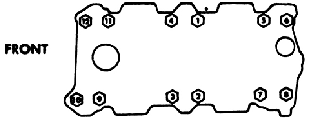


Leave a Reply