


![[Gallery] Street Rodders for Life Memorial Day Car Show](https://www.racingjunk.com/news/wp-content/uploads/2026/06/Memorial-day-show_0198-376x206.jpg)
![[Gallery] Townsman Car Show](https://www.racingjunk.com/news/wp-content/uploads/2026/05/916_2843-e1780072552171-376x206.jpg)

Earl's Transmission Coolers Part 3
Last issue, we began our look at transmission coolers (heat exchangers). This time around, we’ll look at the different types of coolers available. Some are cheap. Some are expensive. Some are poor quality. Some are outstanding quality (and as we all know cheap and high quality can seldom be used in the same sentence!). Check it out:
For the most part two types of cooler styles are readily available: These include a "tube and fin" configuration as well as a "stacked plate" or "modular" configuration.
Typically, the tube and fin cooler models are the most common arrangement you’ll find. With this layout, the cooler consists of a series of fins placed over aluminum tubes, which are in turn, arranged in "S" patterns. The idea behind this is to draw air over the fins, allowing for a heat sink effect that withdraws heat from the transmission fluid. It’s a relatively simple arrangement -- easy to build and inexpensive.
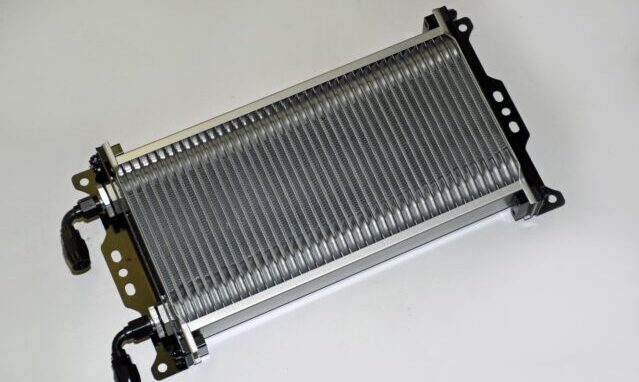
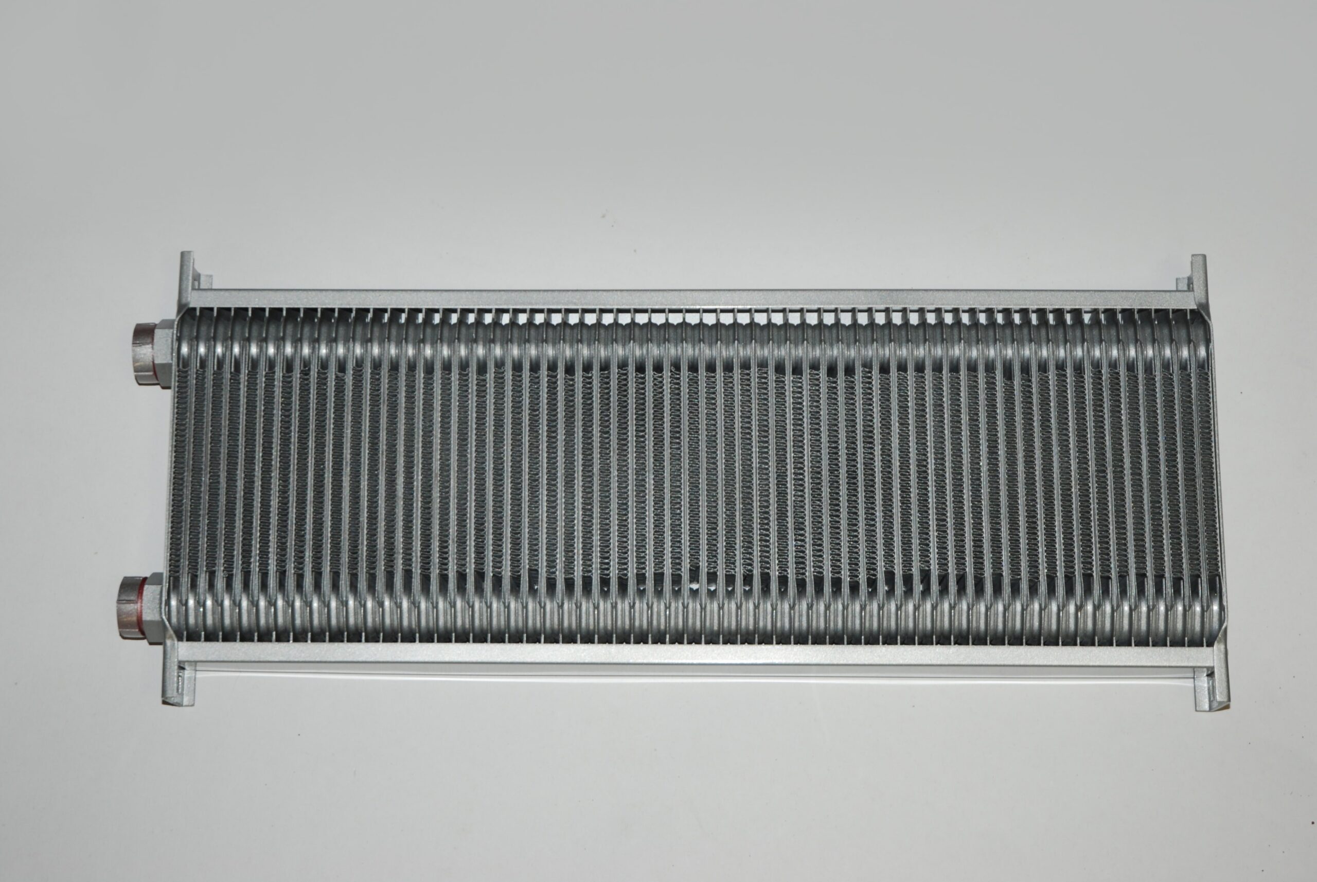
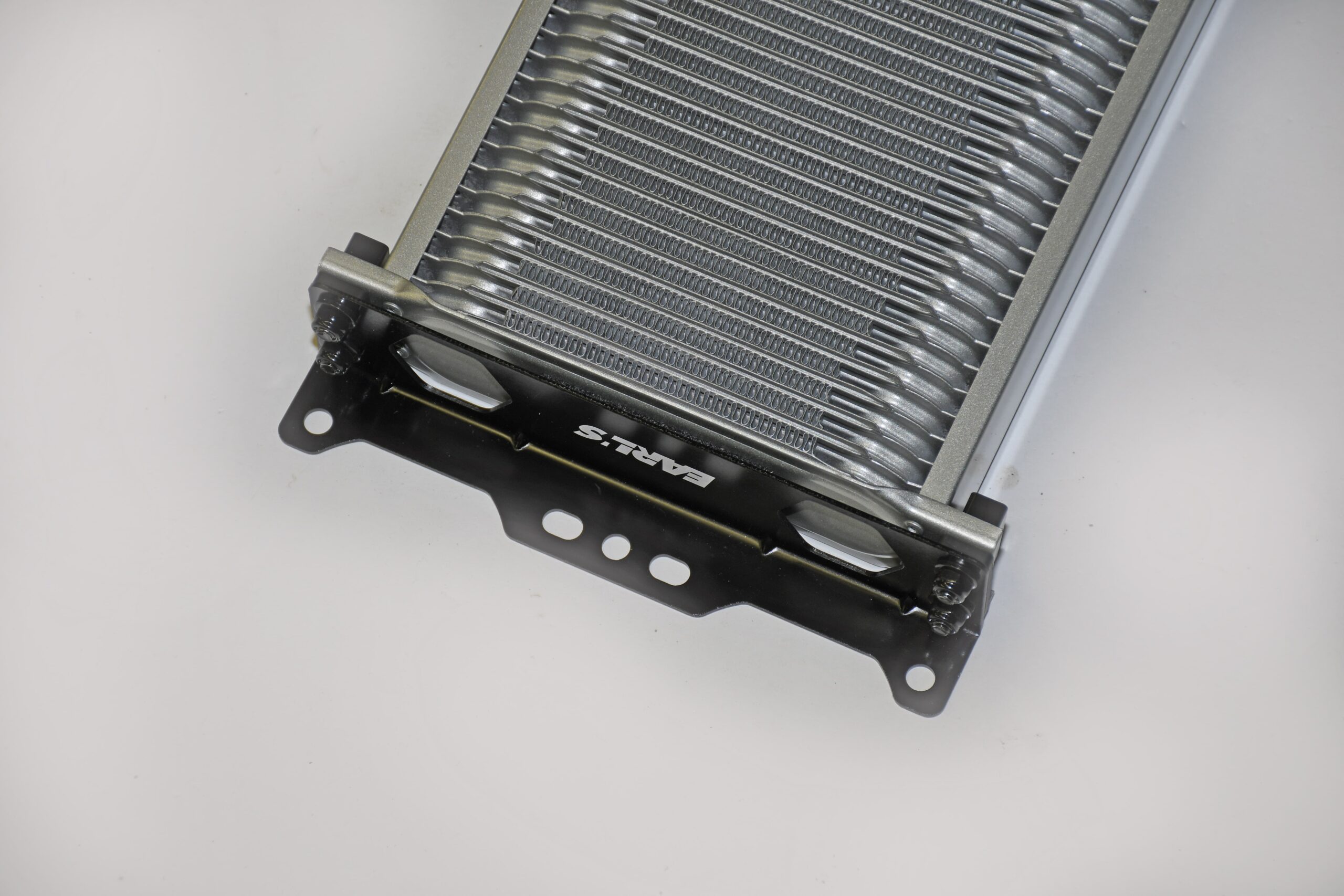
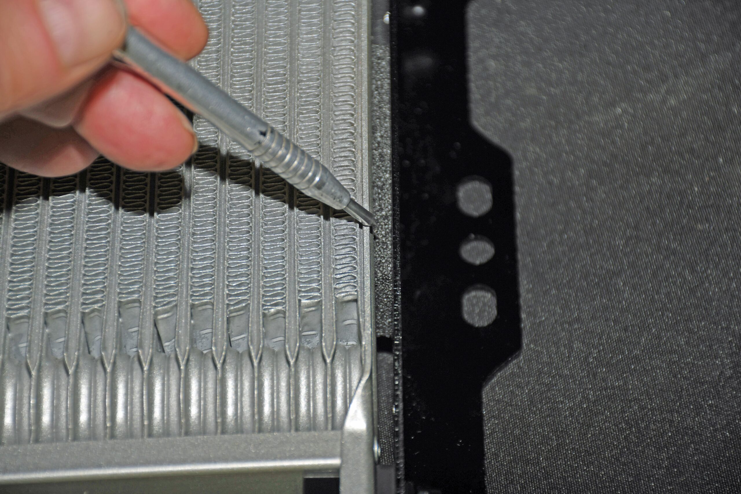
The "stacked plate" design is altogether different. Here, the transmission cooler is arranged similar to that of a modern automotive radiator. Instead of using a tube to carry the transmission fluid inside the cooler, the fins actually form the passage for the fluid to pass through. In operation, this cooler configuration proves much more efficient and much more robust than the tube and fin examples. There’s more to it too:
The stacked plate cooler (sometimes referred to as a "modular" cooler) has been in use prior to WWII. During the early thirties, it was first developed for use with the Rolls Royce Merlin engine that powered the Spitfires and Hurricanes in the Battle of Britain and the same engine that powered the P51 Mustang. This type of cooler incorporates dense air fins and "tubulator plates".
These plates allow for maximum liquid side (internal) and maximum airside (external) surface area. The collector or end tanks ensure minimum flow restriction, while the fully brazed construction results in the most efficient possible thermal transfer bath between liquid and air. A well-engineered heat exchanger will also be laid out so as to insure there is minimal coolant (in our case, automatic transmission fluid) pressure drop between the inlet and outlet ports. The bottom line here is, the old Rolls Royce Merlin design is the likely one of the most thermally efficient liquid to air heat exchanger formats available even today. That’s why the Earl’s coolers shown in the accompanying photos work so well.
Certainly, there are big differences between the conditions seen in an aircraft and those experienced by my street driven car. But there are also a lot of similarities. Those old war birds were obviously piston-engine powered and subsonic when it came to speed. Some of the research that went into the cooling systems of those airplanes dates back to the early days of flight (and in truth, there’s a lot of research that went into them). A heat exchanger or cooler doesn't know or care if it's cooling engine oil or hydraulic fluid or engine coolant. When compared to today’s warbirds, those old aircraft were dead slow and because of that, heat exchanger technology actually has more in common with today's cars than one might think. Bottom line here is, when the stacked plate (modular) layout is incorporated into a cooler, and the oil flow and air speed of the vehicle is taken into consideration (during manufacture), then the optimum heat exchanger can be produced.
So what’s more effective – a modular stacked plate cooler or a common tube and fin arrangement? Typically, a modular cooler (such as the Earl's coolers shown in the photos) will reject as much as three times the heat (for a given area) than a tube and fin cooler. That’s a lot, but there’s also another big consideration and that's coolant (or oil if used as an engine oil cooler) pressure drop: In operation, a modular configuration cooler will have less than half of the pressure drop found in a tube and fin design.
When it comes to cooler configurations, what's best the material -- copper and brass or aluminum? In most cases, the aluminum exchangers are nearly as efficient from a thermal perspective as the copper and brass models, but significantly lighter. On the downside, the aluminum coolers are more difficult to manufacture and as a result are more costly. Take your pick, but we lean toward the aluminum models. One more point is the actual paint. The common black paint commonly applied by most local radiator shops can actually act as thermal barrier instead of promoting the transfer of heat. A well engineered aluminum heat exchanger will either be anodized or it will have a very thin coat of baked, heat exchanger paint (typically grey or silver or black in color).
That’s a wrap for this issue, but we’re not done yet. Next time around, we’ll take a cooler look at the correct location for a cooler along with the correct way to mount it. We’ll also look at cooler sizing and plumbing. In the meantime, check out the accompanying photos:In the last couple of issues we looked at why transmission coolers are so important along with how they work. We also addressed the two major types of coolers available – inexpensive tube and fin jobs along with more costly stacked plate examples. We’ll wrap up the series with this segment, beginning with transmission cooler mounting:
Mounting shouldn’t be difficult, but there are still some not so great mounting locations. Earl's Performance Products points out: "The cooler must be mounted in a stream of moving air at ambient temperature to operate efficiently. It is not a good idea to mount the oil cooler behind the water radiator where it will receive only heated air. It is not enough to lead air to the cooler -- the heated air must have somewhere to go after it passes through the core. Remember, air always obeys the immutable laws of fluid dynamics. Air will only flow from a region of relatively high pressure to a region of relatively low pressure. Any attempt to convince it to do otherwise is doomed to failure."
What this means is you should always mount a cooler in the airstream ahead of the vehicle radiator (common sense – right?). With this arrangement, the cooler will always be subject to high pressure at the face while the engine fan will always provide for a region of low pressure aft of the cooler.
There are other mounting considerations too, not the least of which is the location of the inlet and outlet ports. The reality is, no heat exchanger (radiators included) work well if the liquid side is filled with air. The worst location for the inlet and outlet ports is where they’re oriented on the bottom. The best arrangement is to have the cooler mounted so that the ports are located on the top. If this isn't possible, the next best situation is where the cooler is mounted on the side so that the ports are laid out horizontally.
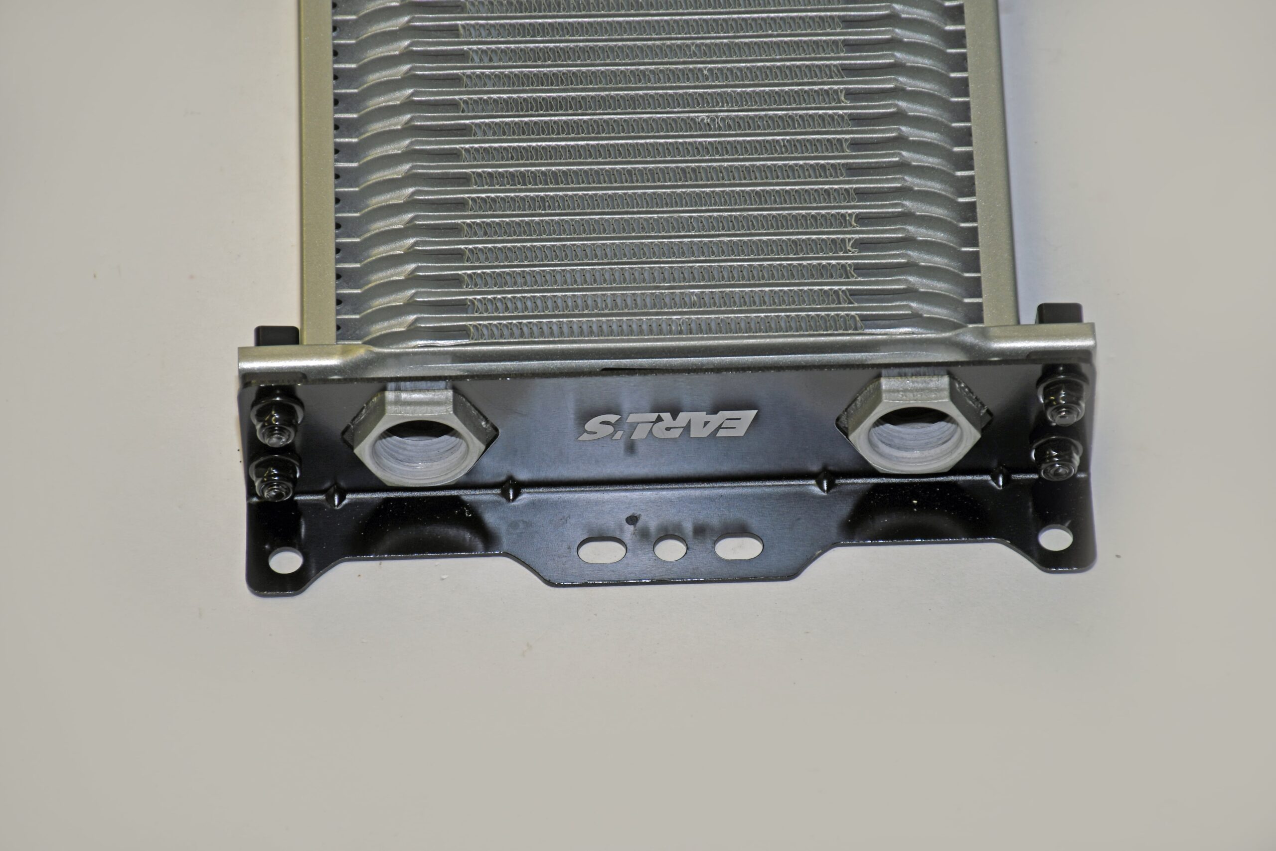
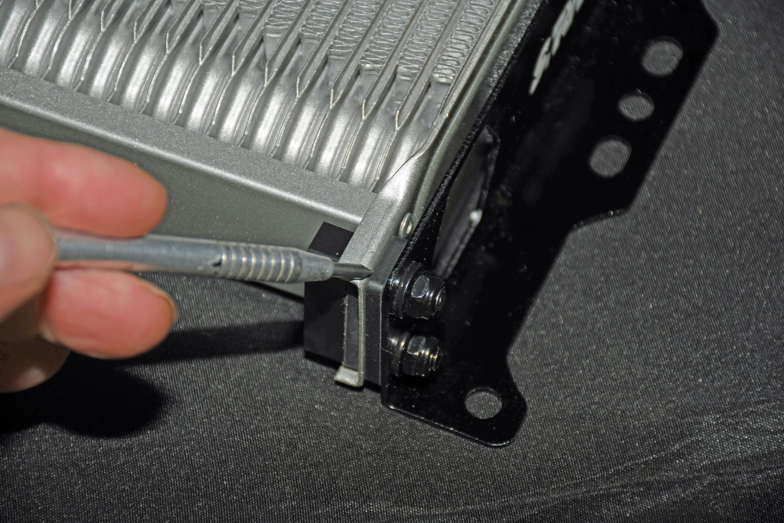
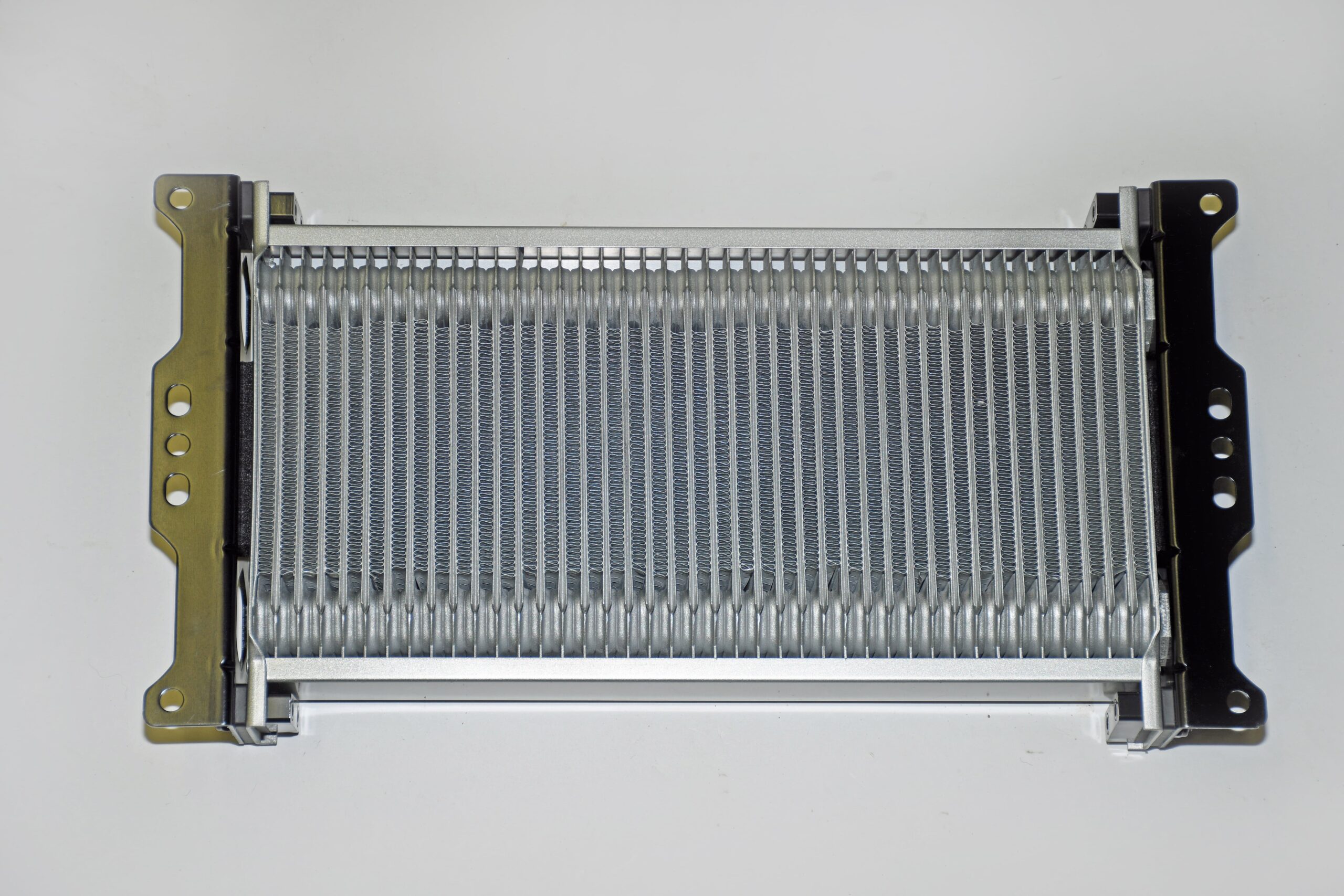
There are several methods you can use to mount a cooler, however Earl’s offers a simple, well-engineered system for their coolers. Manufactured from aluminum, this bracket is designed to hold the cooler securely without damage from vibration. Included is a pair of brackets (with integral rubber cushions) along with e-coated aircraft quality hardware with rubber insulators spacers. Earl's offers this bracket system for all of their Temp-A-Cure cooler models (each with a specific width – more info on various cooler widths below).
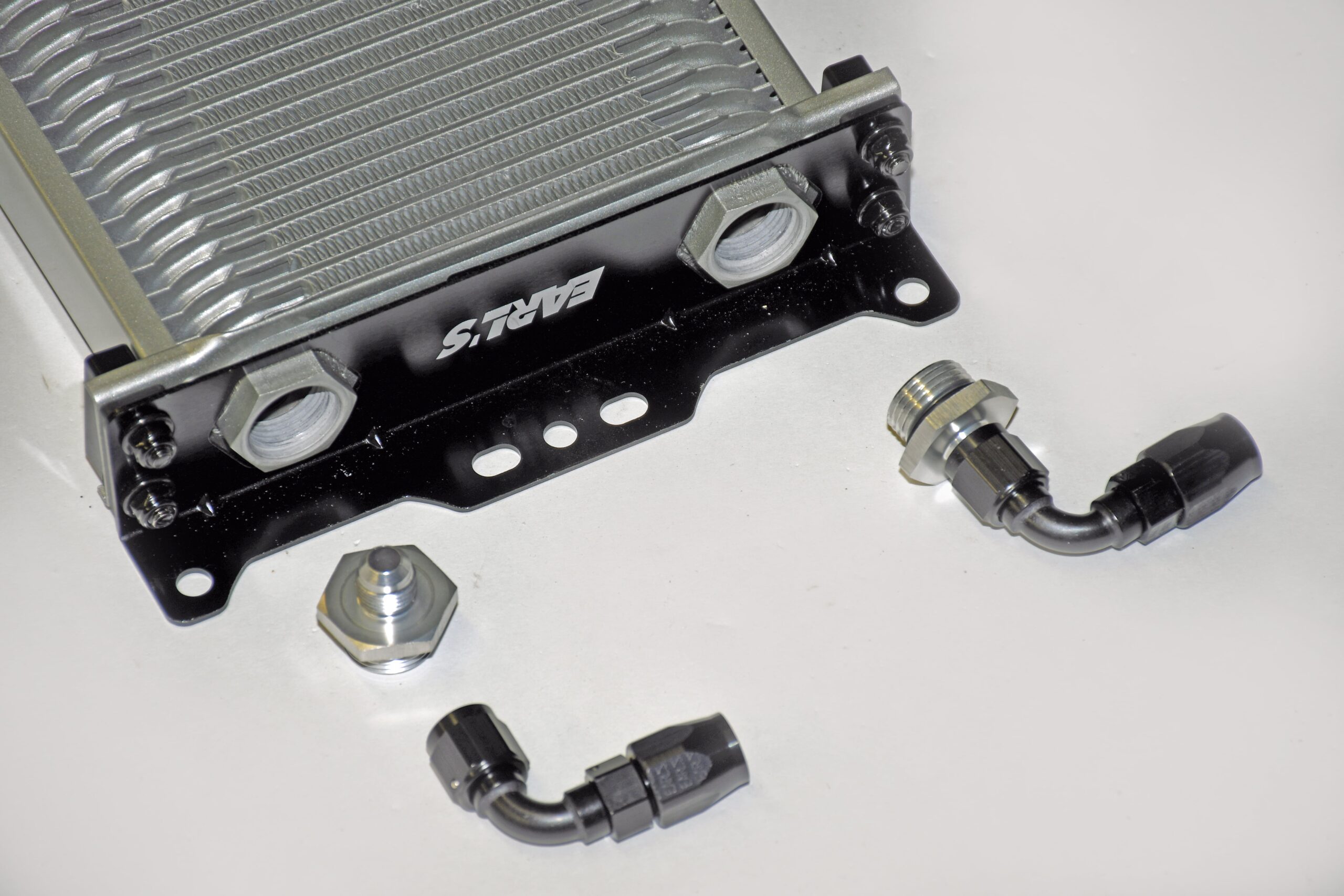
For most high performance (race) automatic transmissions, inlet and outlet ports measuring -6 AN are common. Earl’s coolers typically incorporate a pair of -10 AN O-ring boss ports. From here, it’s pretty easy to pick an AN adapter that suits the application (using our application, a -6 AN to -10 AN arrangement is what we’re using). Yes, you can secure hoses with barb fittings and worm gear clamps. Some coolers use pipe threads. But compared to either of them, AN fittings are less prone to leakage and clearly much more secure.
The final question, and perhaps one of the most critical is cooler sizing. How big should it be? In the case of a high performance street car or truck that is subjected to heavy loads, trailering, etc., then bigger is always better. The pair of heat exchangers shown here measure 8-1/4 X 13-inches and 8-1/4 X 18.5-inches. They’re big. Keep in mind though, it’s pretty much impossible to overcool and automatic. The way the Earl's Temp-A-Cure coolers are designed, allows them to be built in countless sizes. Basically, the folks from Earl's offer a huge range of coolers (“heat exchangers”) to suit almost any application you can dream up. The coolers shown here are narrow 8-1/4-inch wide jobs available in heights that range from 2-inches to 18-1/2 inches. Along with the narrow coolers, Earl’s also offers wide body coolers (width of 13-inches and a height of 2-inches all the way up to 18-inches) along with “extra wide” coolers with a width of 15-1/4 inches and heights range from inches to 18-1/2-inches. That’s a lot of surface area. Additionally, Earl’s manufactures curved coolers. Puzzled? They’re for motorcycle road race applications along with a select few automotive road race applications. They have a width of 11.562-inches and a height from 3.05-inches up to 4.919-inches.
As you can see, there are all sorts of different cooler configurations available. And as we pointed out, you can get a corner auto parts store job or a high-quality race cooler. The choice is yours. But for us, we’ll pick the race cooler any day. They’re more efficient, less troublesome and easier to configure and mount. Cool Aid? No question.
Click Here to Begin Slideshow
For the most part two types of cooler styles are readily available: These include a "tube and fin" configuration as well as a "stacked plate" or "modular" configuration.
Typically, the tube and fin cooler models are the most common arrangement you’ll find. With this layout, the cooler consists of a series of fins placed over aluminum tubes, which are in turn, arranged in "S" patterns. The idea behind this is to draw air over the fins, allowing for a heat sink effect that withdraws heat from the transmission fluid. It’s a relatively simple arrangement -- easy to build and inexpensive.
The "stacked plate" design is altogether different. Here, the transmission cooler is arranged similar to that of a modern automotive radiator. Instead of using a tube to carry the transmission fluid inside the cooler, the fins actually form the passage for the fluid to pass through. In operation, this cooler configuration proves much more efficient and much more robust than the tube and fin examples. There’s more to it too:
The stacked plate cooler (sometimes referred to as a "modular" cooler) has been in use prior to WWII. During the early thirties, it was first developed for use with the Rolls Royce Merlin engine that powered the Spitfires and Hurricanes in the Battle of Britain and the same engine that powered the P51 Mustang. This type of cooler incorporates dense air fins and "tubulator plates".
These plates allow for maximum liquid side (internal) and maximum airside (external) surface area. The collector or end tanks ensure minimum flow restriction, while the fully brazed construction results in the most efficient possible thermal transfer bath between liquid and air. A well-engineered heat exchanger will also be laid out so as to insure there is minimal coolant (in our case, automatic transmission fluid) pressure drop between the inlet and outlet ports. The bottom line here is, the old Rolls Royce Merlin design is the likely one of the most thermally efficient liquid to air heat exchanger formats available even today. That’s why the Earl’s coolers shown in the accompanying photos work so well.
Certainly, there are big differences between the conditions seen in an aircraft and those experienced by my street driven car. But there are also a lot of similarities. Those old war birds were obviously piston-engine powered and subsonic when it came to speed. Some of the research that went into the cooling systems of those airplanes dates back to the early days of flight (and in truth, there’s a lot of research that went into them). A heat exchanger or cooler doesn't know or care if it's cooling engine oil or hydraulic fluid or engine coolant. When compared to today’s warbirds, those old aircraft were dead slow and because of that, heat exchanger technology actually has more in common with today's cars than one might think. Bottom line here is, when the stacked plate (modular) layout is incorporated into a cooler, and the oil flow and air speed of the vehicle is taken into consideration (during manufacture), then the optimum heat exchanger can be produced.
So what’s more effective – a modular stacked plate cooler or a common tube and fin arrangement? Typically, a modular cooler (such as the Earl's coolers shown in the photos) will reject as much as three times the heat (for a given area) than a tube and fin cooler. That’s a lot, but there’s also another big consideration and that's coolant (or oil if used as an engine oil cooler) pressure drop: In operation, a modular configuration cooler will have less than half of the pressure drop found in a tube and fin design.
When it comes to cooler configurations, what's best the material -- copper and brass or aluminum? In most cases, the aluminum exchangers are nearly as efficient from a thermal perspective as the copper and brass models, but significantly lighter. On the downside, the aluminum coolers are more difficult to manufacture and as a result are more costly. Take your pick, but we lean toward the aluminum models. One more point is the actual paint. The common black paint commonly applied by most local radiator shops can actually act as thermal barrier instead of promoting the transfer of heat. A well engineered aluminum heat exchanger will either be anodized or it will have a very thin coat of baked, heat exchanger paint (typically grey or silver or black in color).
That’s a wrap for this issue, but we’re not done yet. Next time around, we’ll take a cooler look at the correct location for a cooler along with the correct way to mount it. We’ll also look at cooler sizing and plumbing. In the meantime, check out the accompanying photos:In the last couple of issues we looked at why transmission coolers are so important along with how they work. We also addressed the two major types of coolers available – inexpensive tube and fin jobs along with more costly stacked plate examples. We’ll wrap up the series with this segment, beginning with transmission cooler mounting:
Mounting shouldn’t be difficult, but there are still some not so great mounting locations. Earl's Performance Products points out: "The cooler must be mounted in a stream of moving air at ambient temperature to operate efficiently. It is not a good idea to mount the oil cooler behind the water radiator where it will receive only heated air. It is not enough to lead air to the cooler -- the heated air must have somewhere to go after it passes through the core. Remember, air always obeys the immutable laws of fluid dynamics. Air will only flow from a region of relatively high pressure to a region of relatively low pressure. Any attempt to convince it to do otherwise is doomed to failure."
What this means is you should always mount a cooler in the airstream ahead of the vehicle radiator (common sense – right?). With this arrangement, the cooler will always be subject to high pressure at the face while the engine fan will always provide for a region of low pressure aft of the cooler.
There are other mounting considerations too, not the least of which is the location of the inlet and outlet ports. The reality is, no heat exchanger (radiators included) work well if the liquid side is filled with air. The worst location for the inlet and outlet ports is where they’re oriented on the bottom. The best arrangement is to have the cooler mounted so that the ports are located on the top. If this isn't possible, the next best situation is where the cooler is mounted on the side so that the ports are laid out horizontally.
There are several methods you can use to mount a cooler, however Earl’s offers a simple, well-engineered system for their coolers. Manufactured from aluminum, this bracket is designed to hold the cooler securely without damage from vibration. Included is a pair of brackets (with integral rubber cushions) along with e-coated aircraft quality hardware with rubber insulators spacers. Earl's offers this bracket system for all of their Temp-A-Cure cooler models (each with a specific width – more info on various cooler widths below).
For most high performance (race) automatic transmissions, inlet and outlet ports measuring -6 AN are common. Earl’s coolers typically incorporate a pair of -10 AN O-ring boss ports. From here, it’s pretty easy to pick an AN adapter that suits the application (using our application, a -6 AN to -10 AN arrangement is what we’re using). Yes, you can secure hoses with barb fittings and worm gear clamps. Some coolers use pipe threads. But compared to either of them, AN fittings are less prone to leakage and clearly much more secure.
The final question, and perhaps one of the most critical is cooler sizing. How big should it be? In the case of a high performance street car or truck that is subjected to heavy loads, trailering, etc., then bigger is always better. The pair of heat exchangers shown here measure 8-1/4 X 13-inches and 8-1/4 X 18.5-inches. They’re big. Keep in mind though, it’s pretty much impossible to overcool and automatic. The way the Earl's Temp-A-Cure coolers are designed, allows them to be built in countless sizes. Basically, the folks from Earl's offer a huge range of coolers (“heat exchangers”) to suit almost any application you can dream up. The coolers shown here are narrow 8-1/4-inch wide jobs available in heights that range from 2-inches to 18-1/2 inches. Along with the narrow coolers, Earl’s also offers wide body coolers (width of 13-inches and a height of 2-inches all the way up to 18-inches) along with “extra wide” coolers with a width of 15-1/4 inches and heights range from inches to 18-1/2-inches. That’s a lot of surface area. Additionally, Earl’s manufactures curved coolers. Puzzled? They’re for motorcycle road race applications along with a select few automotive road race applications. They have a width of 11.562-inches and a height from 3.05-inches up to 4.919-inches.
As you can see, there are all sorts of different cooler configurations available. And as we pointed out, you can get a corner auto parts store job or a high-quality race cooler. The choice is yours. But for us, we’ll pick the race cooler any day. They’re more efficient, less troublesome and easier to configure and mount. Cool Aid? No question.
Click Here to Begin Slideshow
Leave a Reply