

In our last issue, we took a detailed look at MSD’s Pro Billet mechanical advance distributors. If you recall, these CNC machined, billet bodied distributors were loaded with easy-to-use tuning features. They’re plug and play with most MSD ignition boxes too, which makes them extremely attractive from a high performance perspective.
This time around, we’ll step it up and take a look at MSD’s flying magnet crank trigger systems. Why bother with a crank trigger? Ponder this: On something like a high RPM Chevy, the distributor is at the back of the engine. It’s driven by way of the camshaft, which in turn is driven off the crank nose by way of a chain, gear or belt. There’s a gear on the back of the camshaft that lines up and meshes with another gear on the distributor drive shaft. The distributor shaft spins at ½ speed of the crankshaft. The spinning shaft triggers the spark from the ignition and then distributes coil-derived spark to each spark plug. That’s certainly not new-news. There’s more: As profiles on cam lobes become more radical (i.e. “square nose” cams) then valve spring pressure is forced to increase. Engine speeds increase too. Timing chains stretch. Gears wear. Cams twist torsionally. Things start to move around. What happens is there is a point where you can’t maintain accurate or stable timing with a simple distributor, no matter how high the quality. We often refer to the grief as “spark scatter”.
That’s where crank triggers enter the equation. They address spark scatter and ensure rock solid timing right through the engine speed range. Crank trigger setups were first seen in drag racing 40 or so years ago. Essentially, a large wheel (sometimes as big as 8-inches in diameter) was bolted to the snout of the engine (on the harmonic damper). A pickup of sorts sensed the movement of the wheel. And as you can imagine, having a trigger wheel with a diameter of 7 or 8-inches is much more accurate than having a 2-3-inch diameter reluctor inside a distributor cap.
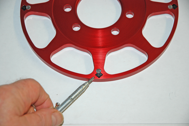
Those early crank triggers were designed with a stationary magnet embedded in the pickup sensor. As the trigger wheel turned, the sensor would detect tabs or studs fitted with steel inserts on the outer portion of the wheel and trigger the spark (basically telling the ignition box to “Fire” the coil). It was a simple design and some companies still use it. But MSD came up with another idea. Instead of having a lone magnet in the pickup, MSD’s “flying magnet” crank trigger design has a series of magnets in the wheel. The magnets pass by a non-magnetic pickup, which trigger the ignition signal. A flying magnet layout is much more reliable, since it cannot be falsely triggered by bolts, race track debris or engine vibration.
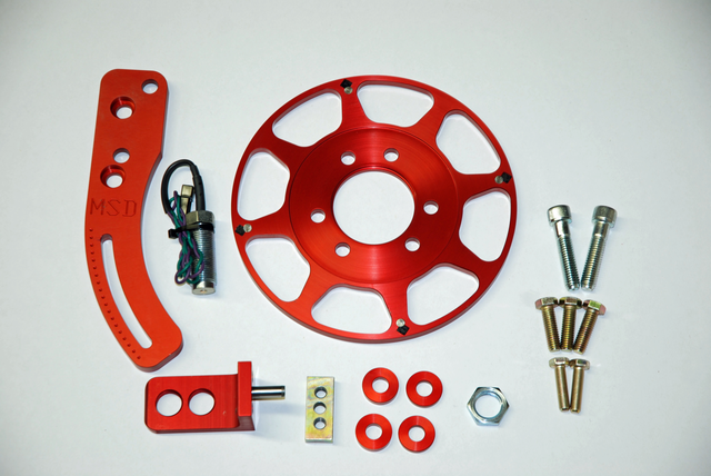
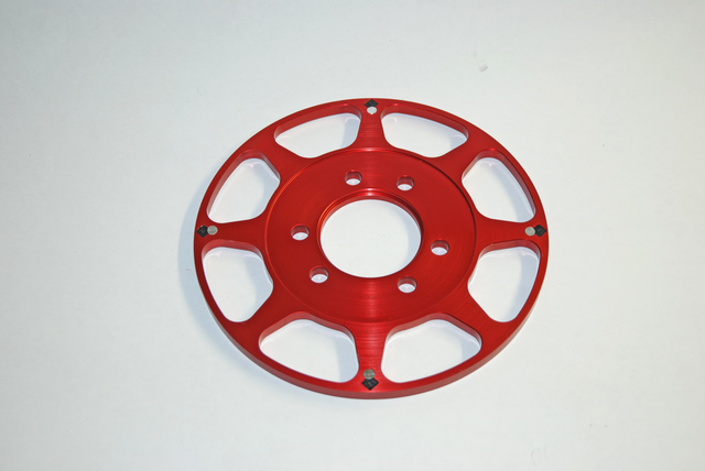
In terms of construction, MSD’s Flying Magnet Crank Trigger makes use of four magnets secured in a billet aluminum trigger wheel that pass by a stationary non-magnetic pick-up to trigger the ignition. This “flying magnet” design produces accurate trigger signals and the non-magnetic pick-up cannot be false triggered.
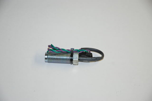
MSD points out the non-magnetic pickup acts much like a coil: “The wires are wound around a small piece of iron so that when the magnet passes the pickup a voltage signal is created. This signal is what triggers the MSD Ignition Control. Like other pickups, the wiring is polarity sensitive. The Violet wire is Positive and the Green wire is Negative. The resistance of the pickup should be 65 – 85 ohms. MSD offers replacement Non- Magnetic Pickups as PN 8276 for Crank Triggers. During installation, twist the wires of the pickup together several times before connecting it to the MSD wiring harness. Twisting these wires together helps reduce the chances of Electro Magnetic Interference (EMI). Route the pickup harness along the chassis or engine block. This provides a ground plane that protects against EMI. Do not run the trigger wires alongside the coil primary wiring or spark plug wires. There are high voltages running through these wires so they should not be close to the pickup wires. Never use solid core spark plug wires with an MSD Ignition system or crank trigger. A helically or spiral wound suppression wire such as MSD’s Street Fire Wires or 8.5mm Super Conductor Wire must be used. If you are running a digital ignition control or aftermarket EFI system, it is highly recommended to use a shielded harness, PN 8862, to prevent the chance of EMI interfering with the trigger signals.”
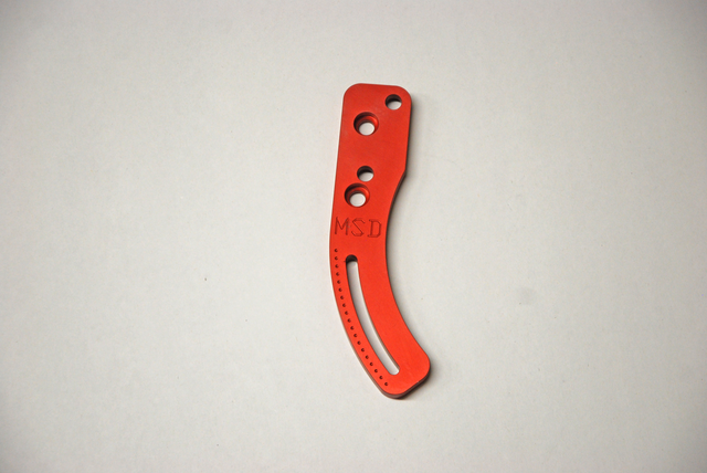
Each MSD Flying Magnet Crank Trigger system includes a two-piece mounting bracket for the non-magnetic pick-up that in Chevy applications will work on either the passenger side or the driver side of the engine (SB Chrysler and SB Ford brackets mount on one side only). The CNC-machined aluminum bracket securely holds the pick-up in place and is slotted to provide a wide range of timing adjustment. MSD includes spacers that allow you to mount the bracket on engines with conventional side motor mounts or by way of a 0.250-inch thick front motor plate. They’re designed to trigger MSD 6, 7 and 8 Series Ignitions, Power Grid systems and they’ll function with all MSD Timing Accessories.
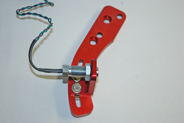
Once the trigger wheel is installed, you have to adjust the air gap between the pickup and the trigger wheel. According to MSD: “The air-gap between the trigger wheel and the non-magnetic pickup is important to the operation of the crank trigger system, however its adjustment does not affect engine power or performance. The proper air-gap will result in a good trigger signal at cranking rpm through high rpm with no interference to the wheel. The optimum setting is generally between 0.050″ – 0.080″.”
With the air gap set, the next consideration is the distributor. If the distributor in your engine is equipped with a centrifugal advance assembly, it must be locked out (either by welding or bolting the advance mechanism). When a crank trigger is installed, the distributor does nothing except distribute high voltage spark created by the coil to the respective spark plugs. This also means there is no timing curve available for the engine (locked out timing). If you need a timing curve, then you’ll likely require something like a Power Grid system that includes the capability of setting up a wide range of specific curves and timing retards. In addition MSD offers other solutions such as starter retard devices, start and step retards and so on to allow for easier starting and of course, timing reduction (retards) on gear changes.
So far so good, but how do you actually time the engine? Instead of moving the distributor, the timing is set by sliding the pickup holder assembly up or down in the bracket slot. In order to retard the timing, move the pickup holder assembly in the direction that the crank trigger wheel rotates. To advance the timing, move the pickup holder assembly in the opposite direction of the trigger wheel rotation. Then you check the timing. Do not attempt to adjust the timing while the engine is running! Always double-check the air-gap whenever the timing is changed.
In our next issue, we’ll take a closer look at MSD’s dedicated crank trigger distributor. In the mean time, check out the accompanying crank trigger photos:
Leave a Reply