
 Hidden High Flow Fuel Delivery System Part 4")
![[Gallery] 3rd. Annual Father's Day Classic Car Show](https://www.racingjunk.com/news/wp-content/uploads/2026/07/Calistoga-2026-18-scaled-e1783026475349-376x206.jpg)

![[Gallery] Blackhawk Museum Stop Over](https://www.racingjunk.com/news/wp-content/uploads/2026/06/DSC_0918-e1782449621944-376x206.jpg)
Building a (Semi) Hidden High Flow Fuel Delivery System Part 4
Click Here to Begin Slideshow
We’re in the homestretch with our stealthy “Covert Ops” fuel system. If you recall, we based the works on a Holley HydraMat and followed up with a heavily reworked stock tank (that, on the outside, still appeared bone stock). With this segment, we’ll show you how it was all plumbed. Follow along:
The intent of the plumbing job was to deliver a high volume of fuel to the carburetor and set it up so that unused fuel returns to the tank (not deadheading). Simultaneously, we wanted to keep the plumbing out of the way (more or less hidden) and tucked up so it wouldn’t be vulnerable to road debris.
We had a couple of good options for fuel lines. Our tried and true, go-to fuel line is Earl’s Perform-O-Flex. It’s a stainless braid-protected synthetic rubber hose. This is a premium quality racing hose, widely used in just about all racing venues across the globe. The reinforced inner hose liner is bonded to a full-coverage outer protective sheath of high tensile stainless steel wire braid. It remains flexible at temperatures between -40 and +350 degrees F and is compatible with almost all fluids used in motorsports (including race gasoline and methanol). Equally important, Perform-O-Flex is easy to work with (that is, compatible with several different types of hose ends including our other go-to plumbing component, Earl’s Swivel Seal).
Our other option was Earl’s Ultra Pro. This is a Teflon-lined (PTFE) hose that is available with either a stainless braid covering or a fabric (polyester) braid covering. The polyester braid covered hose is much lighter than Perform-O-Flex (approximately 67% lighter per length). In addition, it’s pretty much impervious to any additives you might encounter in pump gasoline. In terms of assembly, it’s really not difficult when compared to Perform-O-Flex, but it does require a different process. Finally, the hose ends are specific to the Ultra Pro hose.
We’ve covered hose assembly in the past with a detailed 8-part series. To recap, you can begin with Part 1 here (there’s no point re-hashing this; the comprehensive series covers assembling both Perform-O-Flex and Ultra Pro hose).
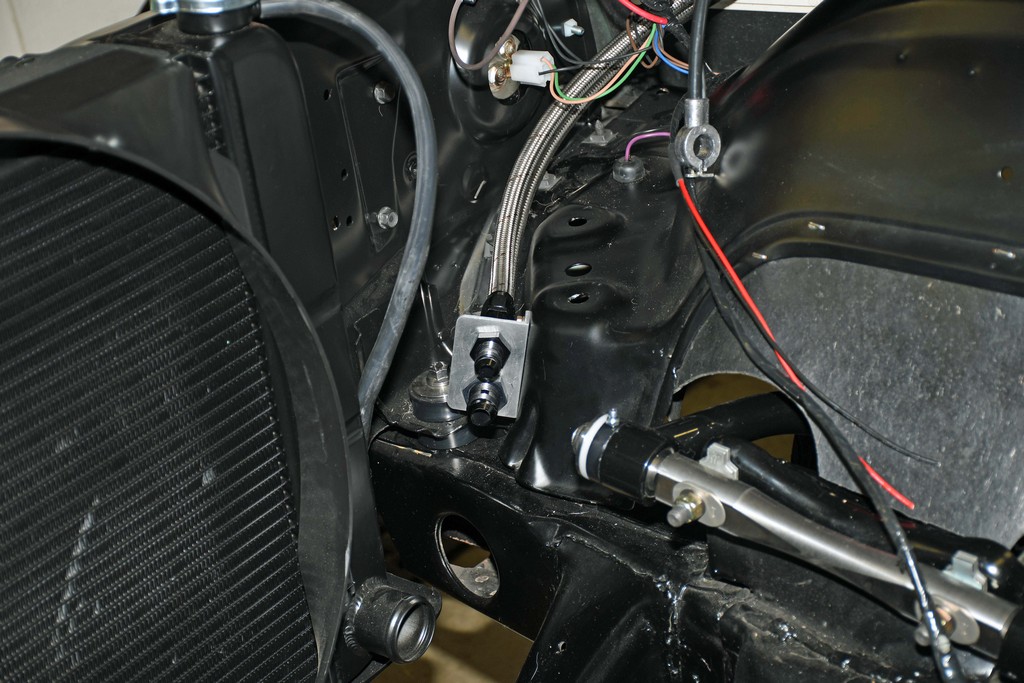
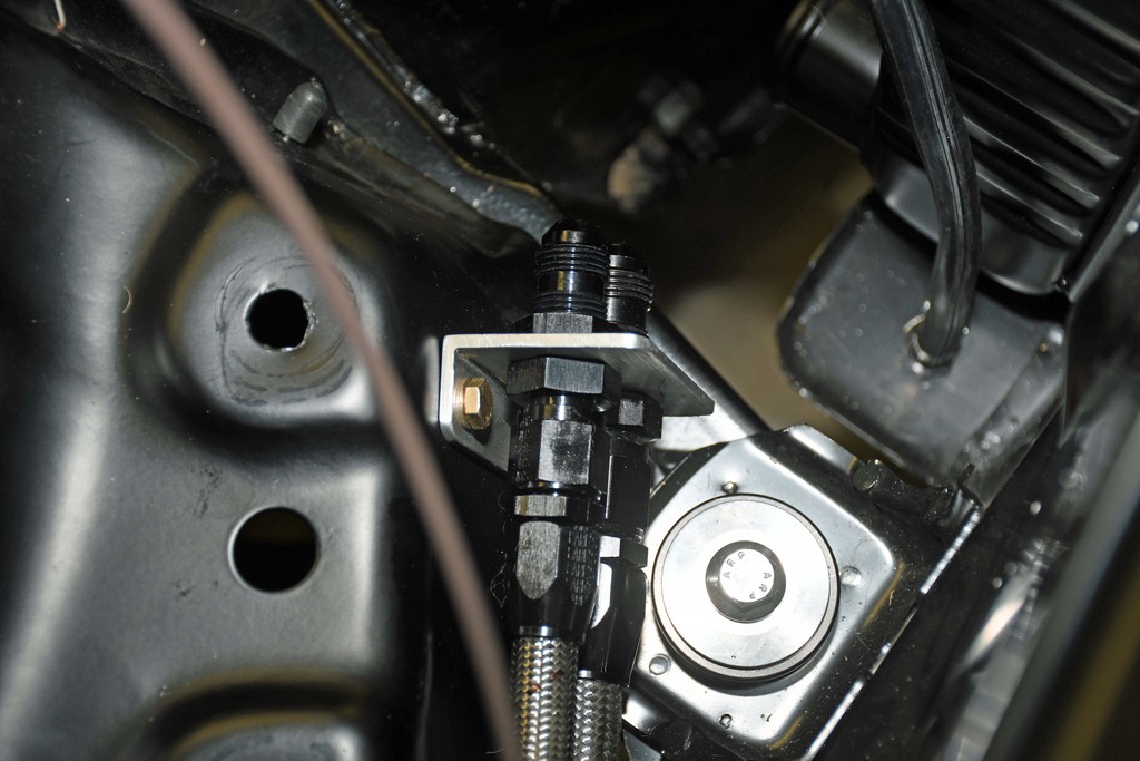
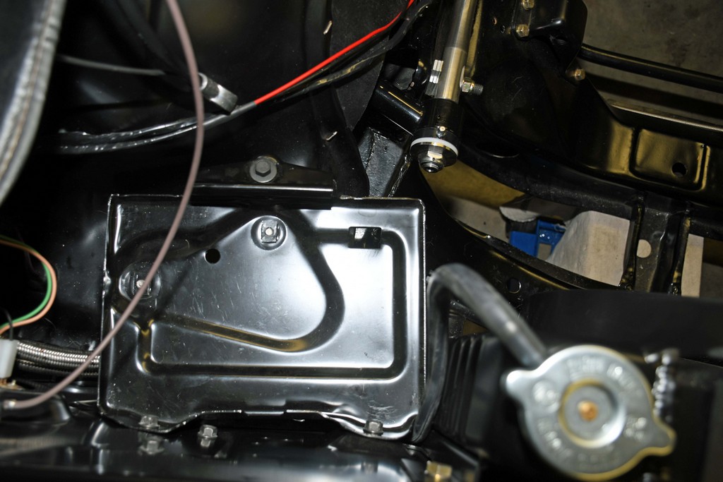
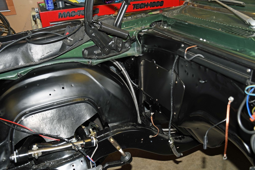
When routing the line, we started at the front of the car and worked our way back. For this application, we built a bulkhead plate to mount the feed and return lines more or less hidden underneath the OEM battery tray in the engine compartment. The -10 feed line will then go to a billet Holley mechanical fuel pump. We don’t have the engine in the car so we can’t finish that part of the plumbing. After the fuel goes to the carb, it returns to a regulator, which hooks up to the -8 bulkhead return line fitting under the battery tray (again, this isn’t complete because there is no engine in the car).
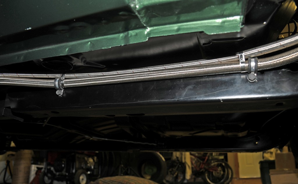
From the battery tray going back to the tank, the pair of lines were routed over the top of the inner fender and then down along the curbside of the frame rail and frame connector. The reason for this routing map is to keep the fuel line away from the headers and the exhaust system. It also serves to keep the line away from the drivetrain of the car. Down below, the lines were also mounted as high as possible in order to keep them away from any potential scrub line interference.
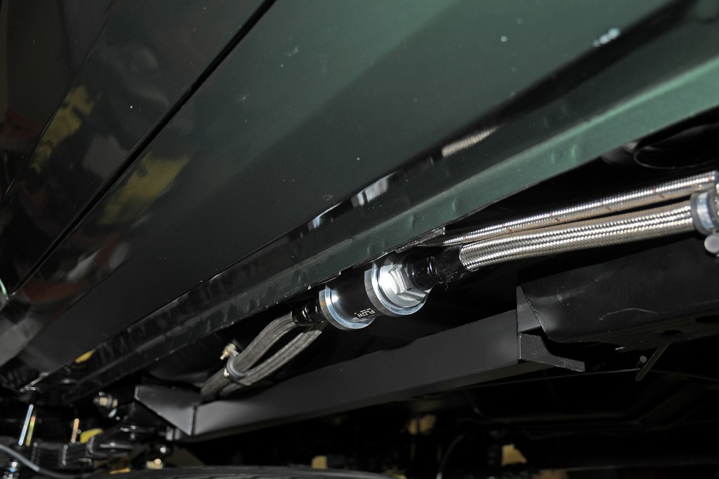
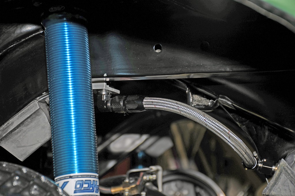
A big Holley billet inline fuel filter was mounted under the passenger seat area. Due to the irregular shape of the floor pan, four spacers were required to locate the filter. This arrangement allowed for easy access to the filter (keep in mind, the HydraMat also acts as a pre-filter). From this point, the pair of fuel lines follow the frame connector, then loop over the top of the passenger side frame connector to join the inner side of the rear subframe. Finally, pressure and return lines hook up to the bulkhead fittings at the leading edge of the gas tank.
The vent line runs up from the top of the tank to a fabricated bracket on the inside of the driver’s side rear subframe. There, a bulkhead fitting hooks to a simple billet breather. The idea here is to keep the vent line (breather) as high as possible in the chassis.
To secure the line, we used a mix of Earl’s cushioned clamps along with stainless steel tie wraps. In order to keep everything tight, the big -10 line was clamped at regular intervals while the -8 return line was tied directly to the -10 hose.
In the end, the covert fuel system turned out almost invisible. We’ve used similar systems in the past and they flat work, provided you use the right mix of components. We must stress again that the fuel pump (in our case, a big Holley billet mechanical) must be able to pull a prime, the tank must have a tight fitting non-vented cap (Stant has several options) and the tank must be externally vented.
For a closer look at the details, check out the accompanying slideshow:
We’re in the homestretch with our stealthy “Covert Ops” fuel system. If you recall, we based the works on a Holley HydraMat and followed up with a heavily reworked stock tank (that, on the outside, still appeared bone stock). With this segment, we’ll show you how it was all plumbed. Follow along:
The intent of the plumbing job was to deliver a high volume of fuel to the carburetor and set it up so that unused fuel returns to the tank (not deadheading). Simultaneously, we wanted to keep the plumbing out of the way (more or less hidden) and tucked up so it wouldn’t be vulnerable to road debris.
We had a couple of good options for fuel lines. Our tried and true, go-to fuel line is Earl’s Perform-O-Flex. It’s a stainless braid-protected synthetic rubber hose. This is a premium quality racing hose, widely used in just about all racing venues across the globe. The reinforced inner hose liner is bonded to a full-coverage outer protective sheath of high tensile stainless steel wire braid. It remains flexible at temperatures between -40 and +350 degrees F and is compatible with almost all fluids used in motorsports (including race gasoline and methanol). Equally important, Perform-O-Flex is easy to work with (that is, compatible with several different types of hose ends including our other go-to plumbing component, Earl’s Swivel Seal).
Our other option was Earl’s Ultra Pro. This is a Teflon-lined (PTFE) hose that is available with either a stainless braid covering or a fabric (polyester) braid covering. The polyester braid covered hose is much lighter than Perform-O-Flex (approximately 67% lighter per length). In addition, it’s pretty much impervious to any additives you might encounter in pump gasoline. In terms of assembly, it’s really not difficult when compared to Perform-O-Flex, but it does require a different process. Finally, the hose ends are specific to the Ultra Pro hose.
We’ve covered hose assembly in the past with a detailed 8-part series. To recap, you can begin with Part 1 here (there’s no point re-hashing this; the comprehensive series covers assembling both Perform-O-Flex and Ultra Pro hose).
When routing the line, we started at the front of the car and worked our way back. For this application, we built a bulkhead plate to mount the feed and return lines more or less hidden underneath the OEM battery tray in the engine compartment. The -10 feed line will then go to a billet Holley mechanical fuel pump. We don’t have the engine in the car so we can’t finish that part of the plumbing. After the fuel goes to the carb, it returns to a regulator, which hooks up to the -8 bulkhead return line fitting under the battery tray (again, this isn’t complete because there is no engine in the car).
From the battery tray going back to the tank, the pair of lines were routed over the top of the inner fender and then down along the curbside of the frame rail and frame connector. The reason for this routing map is to keep the fuel line away from the headers and the exhaust system. It also serves to keep the line away from the drivetrain of the car. Down below, the lines were also mounted as high as possible in order to keep them away from any potential scrub line interference.
A big Holley billet inline fuel filter was mounted under the passenger seat area. Due to the irregular shape of the floor pan, four spacers were required to locate the filter. This arrangement allowed for easy access to the filter (keep in mind, the HydraMat also acts as a pre-filter). From this point, the pair of fuel lines follow the frame connector, then loop over the top of the passenger side frame connector to join the inner side of the rear subframe. Finally, pressure and return lines hook up to the bulkhead fittings at the leading edge of the gas tank.
The vent line runs up from the top of the tank to a fabricated bracket on the inside of the driver’s side rear subframe. There, a bulkhead fitting hooks to a simple billet breather. The idea here is to keep the vent line (breather) as high as possible in the chassis.
To secure the line, we used a mix of Earl’s cushioned clamps along with stainless steel tie wraps. In order to keep everything tight, the big -10 line was clamped at regular intervals while the -8 return line was tied directly to the -10 hose.
In the end, the covert fuel system turned out almost invisible. We’ve used similar systems in the past and they flat work, provided you use the right mix of components. We must stress again that the fuel pump (in our case, a big Holley billet mechanical) must be able to pull a prime, the tank must have a tight fitting non-vented cap (Stant has several options) and the tank must be externally vented.
For a closer look at the details, check out the accompanying slideshow:
Leave a Reply