

![[Gallery] Sacramento Autorama](https://www.racingjunk.com/news/wp-content/uploads/2026/05/916_2154-e1778809267634-376x206.jpg)

![[Gallery] Ancient City Auto Club 41st Annual Car Show](https://www.racingjunk.com/news/wp-content/uploads/2025/12/DSC_9441-1-e1766520816593-376x206.jpg)
Reciprocal Knowledge Part 2: Two Dozen Fast Facts About Cranks & Connecting Rods
Click Here to Begin Slideshow
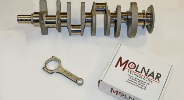
When we left you the last time around, we presented a dozen different fast facts on connecting rods, crankshafts and associated components. Tom Molnar (Molnar Technologies www.molnartechnologies.com) is the brains behind these fast facts. He has decades of experience in the race rod and crank business and we’re extremely fortunate to have to the opportunity to dig into his vast knowledge bank. The idea behind this series was and still is to dispel some of the old wives’ tales out there when it comes to reciprocating parts. Check it out:
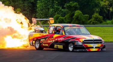
13) Pressure Packed: Connecting rod bolt must never be tightened without lubricant as this can cause them to seize in the rods and become impossible to remove. Never use Loctite, Moly Lube or Oil on bolts. Through many years of testing, Molnar has found CMD Extreme Pressure Lube #3 to be the most consistent and trouble-free lube on the market and the only lube they recommend. This is very important!
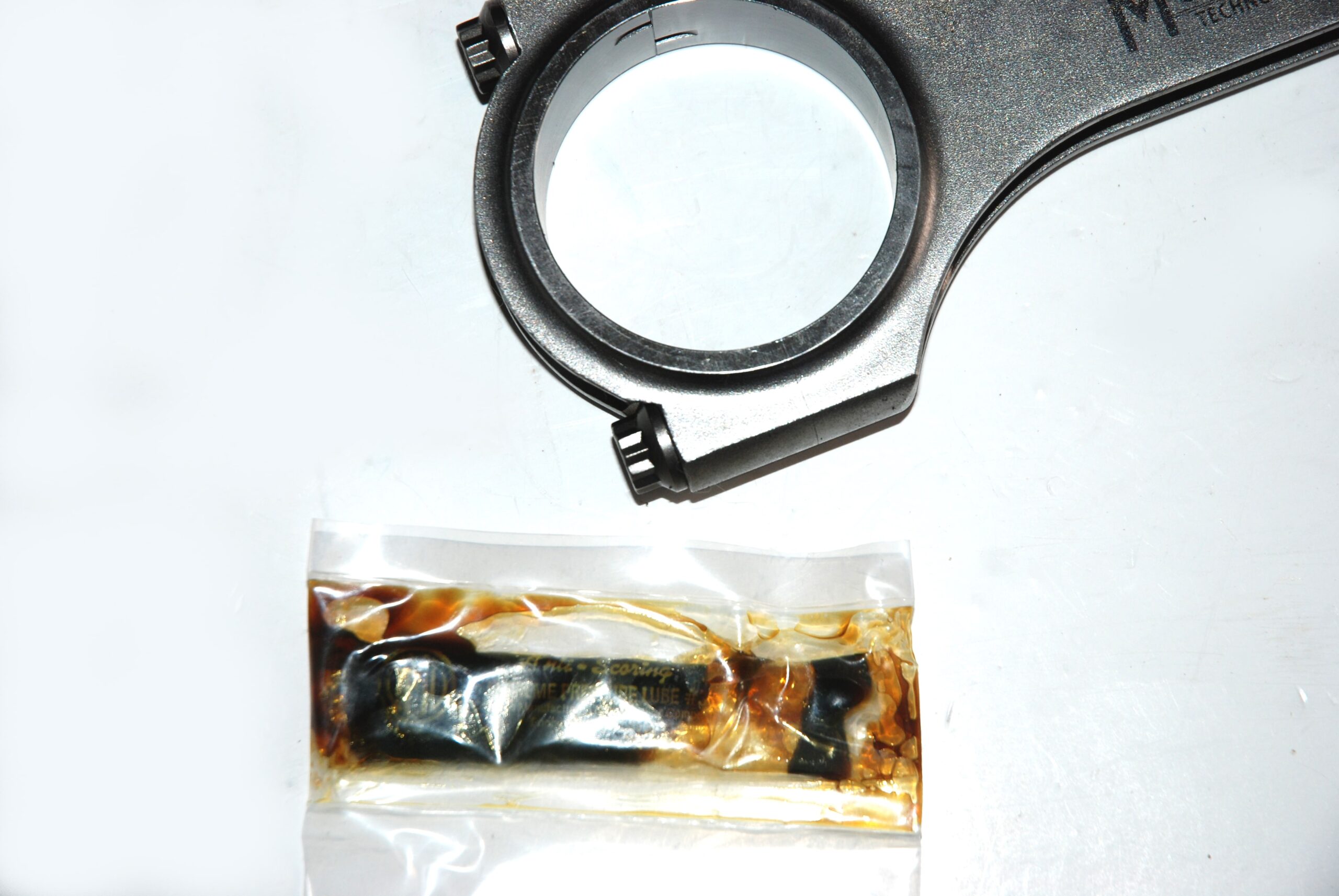
(14) Torque and Angle or Stretch Versus Torque: Molnar advises you use a torque angle or stretch method in order to properly tighten connecting rod fasteners. The reason is bolts are like extremely stiff springs. Stretching them to the proper figure provides the clamp load that is required to keep the parts together. Using a torque wrench does not measure clamp load. It measures friction and with each tightening, the mating surfaces (male / female threads, bolt flange and spotface on the rod) change which means the friction changes and tightening to the same friction level (torque) will not result in the same clamping force of the bolts. Bottom line is, the correct torque is a moving target and you never know what is correct. Stretch on the other hand is a constant and will provide the same clamping force with each tightening. In the torque and angle method, you will tighten to a low torque level where the error factor is low and will simply take the back lash out of the threads then the angle method works directly off from the pitch of the bolt threads to accurately stretch the bolts. Yes, measuring stretch or torque and angle is more difficult but so is picking up broken parts from the racetrack.
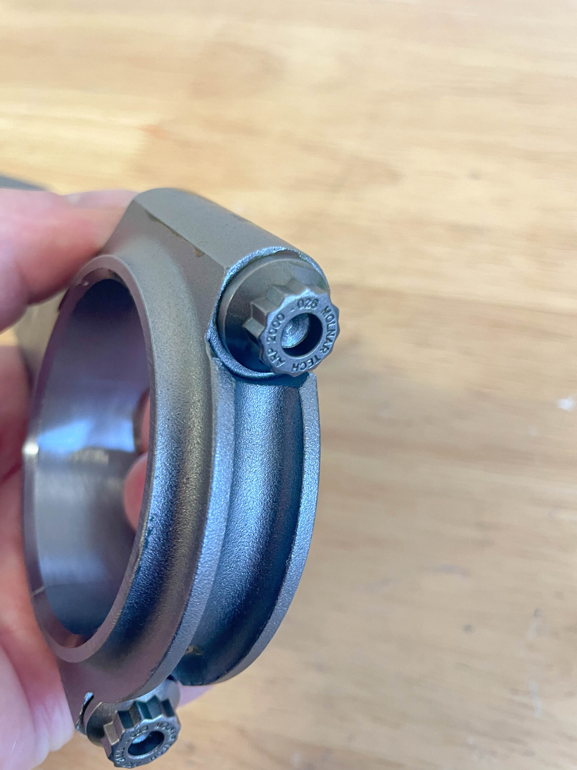
While on this subject, not all ARP2000 bolts are the same. ARP2000 is the MATERIAL not the bolt type. Simply put, you have a 3/8” or 7/16” ARP2000 bolt and they are clearly not the same. This is also true regarding the bolt design. All Molnar connecting rods bolts are custom made for them by ARP and have several features that make them an upgrade over many of the other bolts on the market.
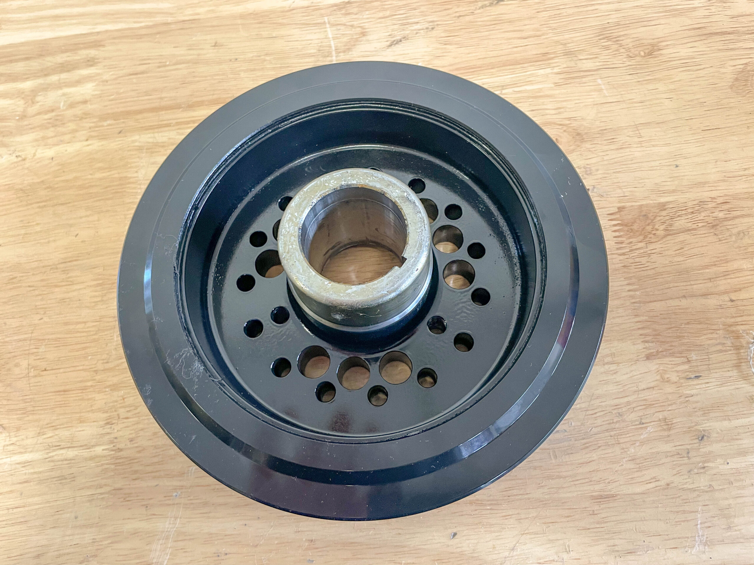
(14) Interference Fit: Harmonic balancers (“dampers”) must have an interference fit to the crankshaft. The amount of clearance depends upon the damper manufacturer. For example, the Power Bond SFI damper shown in the accompanying photos has an interference fit of 0.0011-0.0015-inch for my big block Chevy. Polishing the crank snout is not an option to gain clearance! Instead, the damper bore should be honed.
(15) Anti-Seize: When installing a harmonic damper, use the proper tools and according to the folks from ATI, it is also a good idea to apply a thin coat of anti-seize to the crank snout before installation. This is particularly important if a damper with an aluminum hub is used.
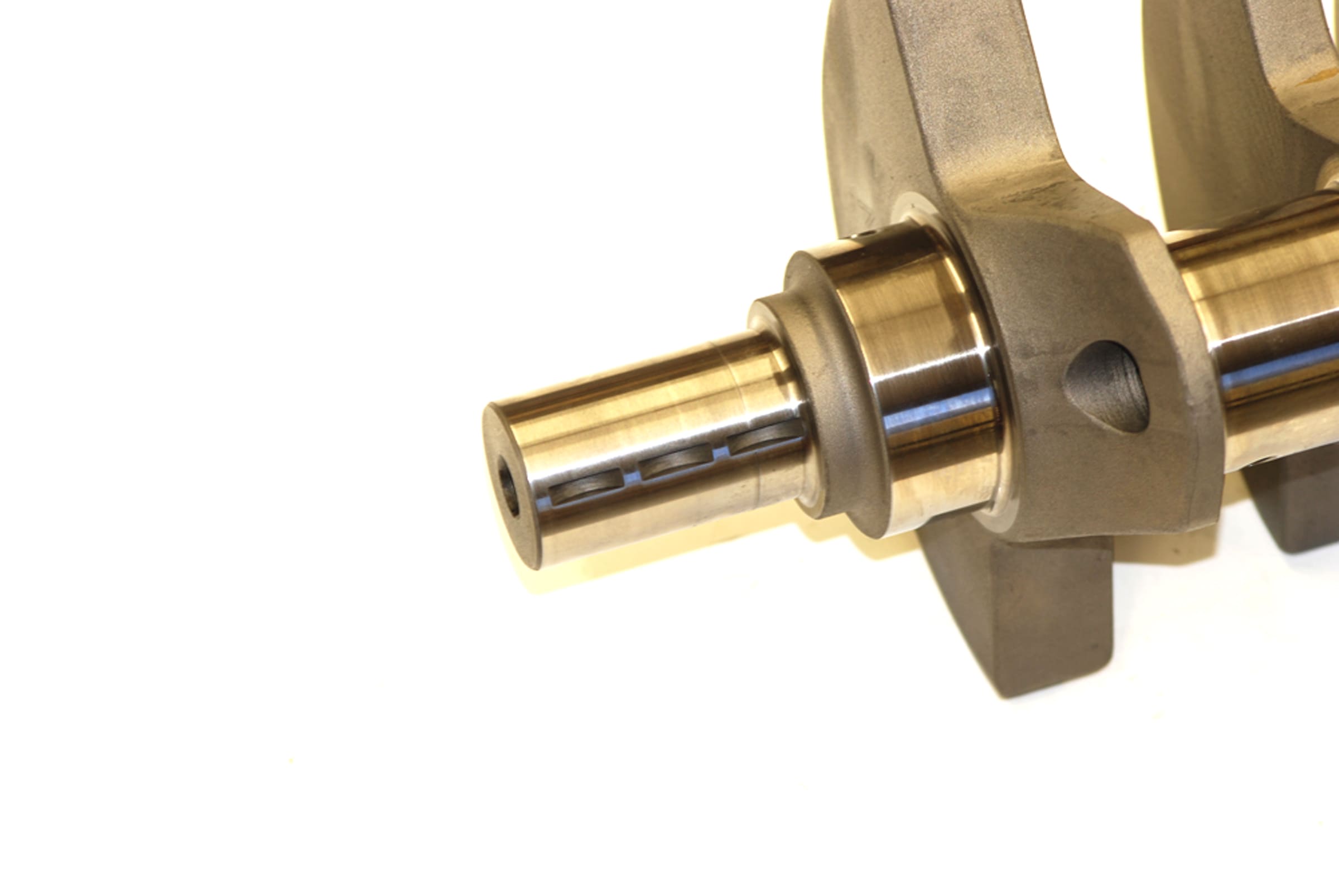
(16) Keyways: Crankshaft keys are cheap! It’s not uncommon to find examples that burrs or nicks. On a similar note, you should always inspect the keyway in the crank for any damage (more common on used crankshafts).
(17) Horsepower Ratings for Connecting Rods: Some manufacturers rate their connecting rods by the horsepower level in an engine. Molnar Technologies does not. Tom Molnar explains: “We all know power is created by the expanding gasses pushing on the piston which in turn pushes on the connecting rod and the energy is used to rotate the crankshaft. There are situations where a rod can break due to these compressive forces however, the loads on a connecting rod are actually more complex than this. These loads include, but are not limited to, unequal forces from wrist pin distortion, excessive bearing clearances, detonation, improper oiling, and tensile loading by the piston at TDC of the exhaust stroke. If you look closely at a broken rod, in most cases you will find it is not crushed from the power cycle and is actually pulled apart from the tensile load. RPM, stroke, piston/pin weight and rod length all affect the tensile load that is placed on the rod. Typically, performance engines are operating at an RPM that is well above peak power. This lower power/high RPM situation may be an accidental over-rev at the end of a straight away, or when the throttle is closed going into a corner or at the end of the drag strip. It is at these elevated revs that the rod will likely become over-stressed and ultimately lead to a failure. Since the causes of rod failures typically occur at power levels that are not at peak power the question comes up as to why power ratings are used to rate rods? The answer is they are a simplistic way to deal with a complicated issue since compressive and tensile loads generally increase with increased power. However, power ratings are not the only thing to consider when making a connecting rod selection. Don’t be fooled by people who provide a simple power rating to sell you parts.”
(18) Horsepower & Rod Bolts: On a similar note, should bolts be changed when horsepower increases? Tom Molnar points out: “Another bolt myth is when a certain HP level is reached, the bolts need to be upgraded. Since power is created when the combustion pressure pushes on the piston and the only load a bolt sees is a tension (pulling) load when the piston reaches TDC on the exhaust stroke, the bolts do not know if the engine is making 100 HP or 1,000 HP. This high-tension pulling load is based on piston / wrist pin / ring weight, stroke and RPM.”
(19) Bearing Crush & Spread: In order to keep the bearing shells from spinning in the rod housing bore, bearing inserts extend past the parting line of the bores in both connecting rods and crankshafts. This is called “Crush”. You will also find that bearings are slightly wider than the bore (when viewed from the side). This is usually called “Spread”, and it helps to keep the bearings in place as the engine is assembled. Both of these characteristics were engineered into the bearing prior to manufacture.
(20) Forging Foul Up: According to Tom Molnar: “The forging process is sort of a myth. When you put a hot bar of steel with grain flow that runs from one end to another into a press, not only does it not close the grain at the top of the part, in most cases, the same forging is used for long and short parts. When a short rod is made from this forging, the end is cut off which leaves open grain. Also punching a hole in the big end does not make the grain circular any more than drilling a hole in the part would change the grain flow. Also, since the forging process is done at such a high temperature, the compressive strength would relax before it cooled. It also does not pick up any tensile strength. This is done during the heat-treating process.”
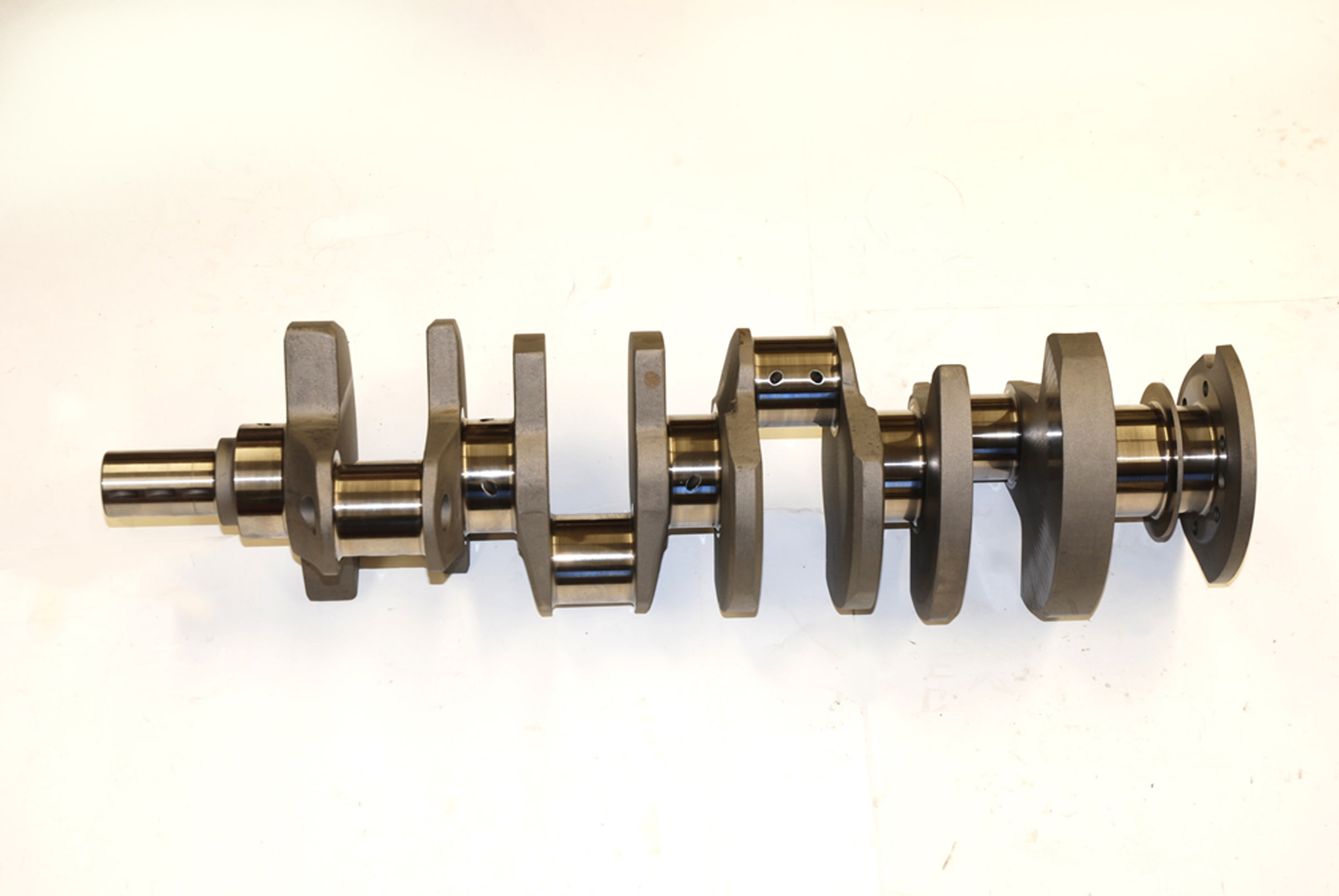
(21) Crankshaft Heat Treatment: How important is heat-treating in a crankshaft? Heat-treating is done to increase tensile and fatigue strength. Nitriding does not increase strength but does provide a very hard wear surface to preserve the size and shape of the bearing surfaces.
(22) The difference between Twist and Non-Twist crankshafts: A non-twist crankshaft requires more complex forging dies that forms the crank with all of the rod pins in the correct location. A “twist” type of forging forms the crank in what looks like a flat plane configuration. The crank is then heated again and the forging is twisted to put the rod pins in their correct location.
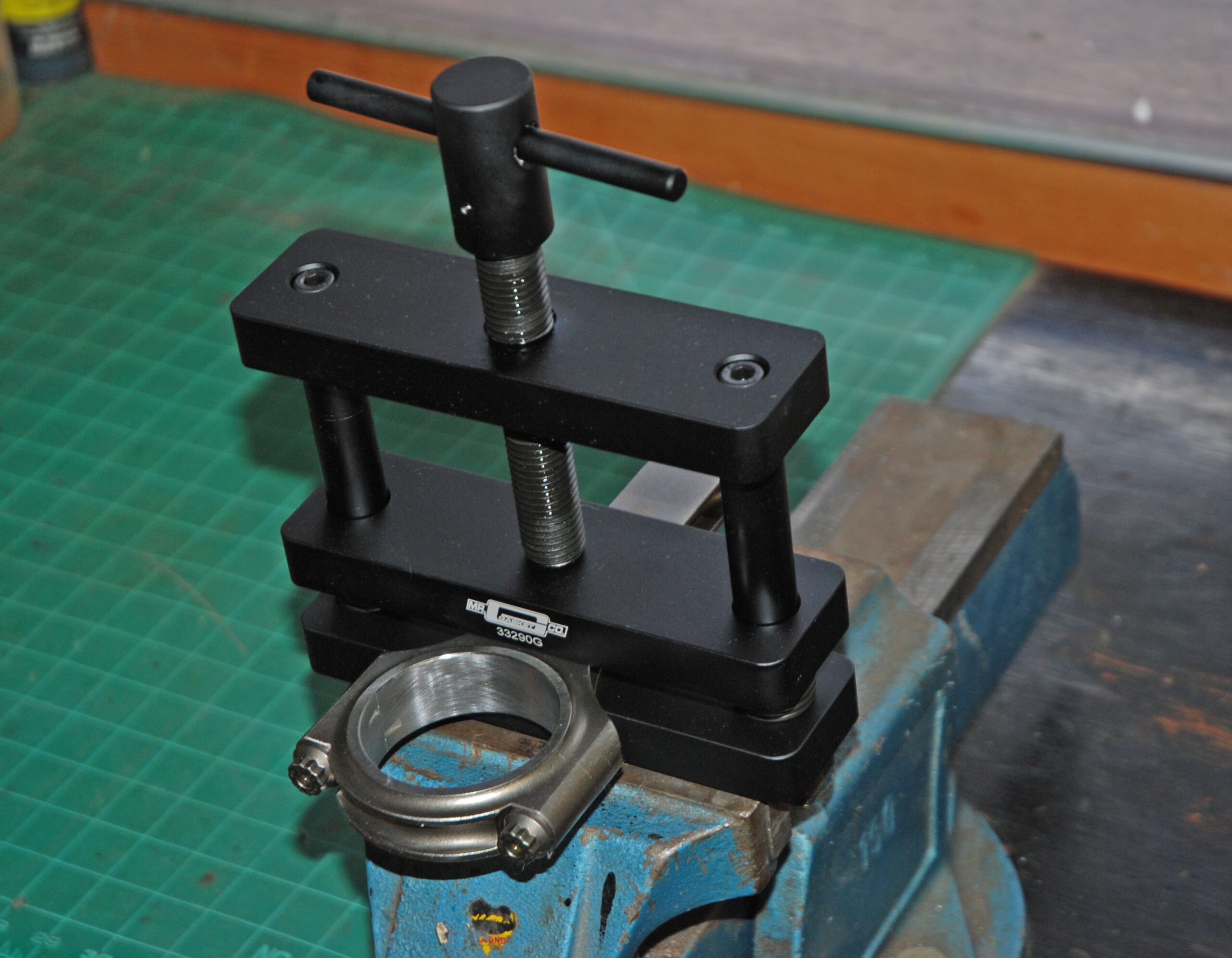
(23) Connecting Rod Vise: A connecting rod vise isn’t an expensive tool, and in today’s world, it’s almost mandatory when working on an engine. Using a rod vise is dirt simple. After it has been clamped in a bench vise or mounted permanently on your workbench, insert a connecting rod (or two) in the rod vise jaws. Tighten the upper t-bolt to secure the connecting rod(s). At this point, you’re ready to go to work. You’ll find it makes chores such as loosening or tightening rod bolts super easy.
(24) Crank Polishing: When a crankshaft is ground, the stones leave a surface finish on the journal that isn’t perfectly smooth. Because of this, journals are most often ground to a size that is very slight larger than the final size. Typically, the journals are 0.0005-inch or so over size. The remaining material is then removed from the journals on a crankshaft-polishing machine. The polishing job requires a large amount of skill. For example, it’s easy enough to polish a crank right into a slight taper. This can occur when the crank is polished in a back-and-forth motion. Here, the polishing job will actually wear the middle the journal more than the other edges. The job of polishing leaves a microscopic “nap” of the metal on the surface of the journal. When the crank is polished, the machinist has to ensure that crankshaft turns in the same direction as it spins inside the engine block. If it isn’t done this way, then the nap that results from the polishing will eventually wear into the bearing surface.
Click Here to Begin Slideshow
When we left you the last time around, we presented a dozen different fast facts on connecting rods, crankshafts and associated components. Tom Molnar (Molnar Technologies www.molnartechnologies.com) is the brains behind these fast facts. He has decades of experience in the race rod and crank business and we’re extremely fortunate to have to the opportunity to dig into his vast knowledge bank. The idea behind this series was and still is to dispel some of the old wives’ tales out there when it comes to reciprocating parts. Check it out:
13) Pressure Packed: Connecting rod bolt must never be tightened without lubricant as this can cause them to seize in the rods and become impossible to remove. Never use Loctite, Moly Lube or Oil on bolts. Through many years of testing, Molnar has found CMD Extreme Pressure Lube #3 to be the most consistent and trouble-free lube on the market and the only lube they recommend. This is very important!
(14) Torque and Angle or Stretch Versus Torque: Molnar advises you use a torque angle or stretch method in order to properly tighten connecting rod fasteners. The reason is bolts are like extremely stiff springs. Stretching them to the proper figure provides the clamp load that is required to keep the parts together. Using a torque wrench does not measure clamp load. It measures friction and with each tightening, the mating surfaces (male / female threads, bolt flange and spotface on the rod) change which means the friction changes and tightening to the same friction level (torque) will not result in the same clamping force of the bolts. Bottom line is, the correct torque is a moving target and you never know what is correct. Stretch on the other hand is a constant and will provide the same clamping force with each tightening. In the torque and angle method, you will tighten to a low torque level where the error factor is low and will simply take the back lash out of the threads then the angle method works directly off from the pitch of the bolt threads to accurately stretch the bolts. Yes, measuring stretch or torque and angle is more difficult but so is picking up broken parts from the racetrack.
While on this subject, not all ARP2000 bolts are the same. ARP2000 is the MATERIAL not the bolt type. Simply put, you have a 3/8” or 7/16” ARP2000 bolt and they are clearly not the same. This is also true regarding the bolt design. All Molnar connecting rods bolts are custom made for them by ARP and have several features that make them an upgrade over many of the other bolts on the market.
(14) Interference Fit: Harmonic balancers (“dampers”) must have an interference fit to the crankshaft. The amount of clearance depends upon the damper manufacturer. For example, the Power Bond SFI damper shown in the accompanying photos has an interference fit of 0.0011-0.0015-inch for my big block Chevy. Polishing the crank snout is not an option to gain clearance! Instead, the damper bore should be honed.
(15) Anti-Seize: When installing a harmonic damper, use the proper tools and according to the folks from ATI, it is also a good idea to apply a thin coat of anti-seize to the crank snout before installation. This is particularly important if a damper with an aluminum hub is used.
(16) Keyways: Crankshaft keys are cheap! It’s not uncommon to find examples that burrs or nicks. On a similar note, you should always inspect the keyway in the crank for any damage (more common on used crankshafts).
(17) Horsepower Ratings for Connecting Rods: Some manufacturers rate their connecting rods by the horsepower level in an engine. Molnar Technologies does not. Tom Molnar explains: “We all know power is created by the expanding gasses pushing on the piston which in turn pushes on the connecting rod and the energy is used to rotate the crankshaft. There are situations where a rod can break due to these compressive forces however, the loads on a connecting rod are actually more complex than this. These loads include, but are not limited to, unequal forces from wrist pin distortion, excessive bearing clearances, detonation, improper oiling, and tensile loading by the piston at TDC of the exhaust stroke. If you look closely at a broken rod, in most cases you will find it is not crushed from the power cycle and is actually pulled apart from the tensile load. RPM, stroke, piston/pin weight and rod length all affect the tensile load that is placed on the rod. Typically, performance engines are operating at an RPM that is well above peak power. This lower power/high RPM situation may be an accidental over-rev at the end of a straight away, or when the throttle is closed going into a corner or at the end of the drag strip. It is at these elevated revs that the rod will likely become over-stressed and ultimately lead to a failure. Since the causes of rod failures typically occur at power levels that are not at peak power the question comes up as to why power ratings are used to rate rods? The answer is they are a simplistic way to deal with a complicated issue since compressive and tensile loads generally increase with increased power. However, power ratings are not the only thing to consider when making a connecting rod selection. Don’t be fooled by people who provide a simple power rating to sell you parts.”
(18) Horsepower & Rod Bolts: On a similar note, should bolts be changed when horsepower increases? Tom Molnar points out: “Another bolt myth is when a certain HP level is reached, the bolts need to be upgraded. Since power is created when the combustion pressure pushes on the piston and the only load a bolt sees is a tension (pulling) load when the piston reaches TDC on the exhaust stroke, the bolts do not know if the engine is making 100 HP or 1,000 HP. This high-tension pulling load is based on piston / wrist pin / ring weight, stroke and RPM.”
(19) Bearing Crush & Spread: In order to keep the bearing shells from spinning in the rod housing bore, bearing inserts extend past the parting line of the bores in both connecting rods and crankshafts. This is called “Crush”. You will also find that bearings are slightly wider than the bore (when viewed from the side). This is usually called “Spread”, and it helps to keep the bearings in place as the engine is assembled. Both of these characteristics were engineered into the bearing prior to manufacture.
(20) Forging Foul Up: According to Tom Molnar: “The forging process is sort of a myth. When you put a hot bar of steel with grain flow that runs from one end to another into a press, not only does it not close the grain at the top of the part, in most cases, the same forging is used for long and short parts. When a short rod is made from this forging, the end is cut off which leaves open grain. Also punching a hole in the big end does not make the grain circular any more than drilling a hole in the part would change the grain flow. Also, since the forging process is done at such a high temperature, the compressive strength would relax before it cooled. It also does not pick up any tensile strength. This is done during the heat-treating process.”
(21) Crankshaft Heat Treatment: How important is heat-treating in a crankshaft? Heat-treating is done to increase tensile and fatigue strength. Nitriding does not increase strength but does provide a very hard wear surface to preserve the size and shape of the bearing surfaces.
(22) The difference between Twist and Non-Twist crankshafts: A non-twist crankshaft requires more complex forging dies that forms the crank with all of the rod pins in the correct location. A “twist” type of forging forms the crank in what looks like a flat plane configuration. The crank is then heated again and the forging is twisted to put the rod pins in their correct location.
(23) Connecting Rod Vise: A connecting rod vise isn’t an expensive tool, and in today’s world, it’s almost mandatory when working on an engine. Using a rod vise is dirt simple. After it has been clamped in a bench vise or mounted permanently on your workbench, insert a connecting rod (or two) in the rod vise jaws. Tighten the upper t-bolt to secure the connecting rod(s). At this point, you’re ready to go to work. You’ll find it makes chores such as loosening or tightening rod bolts super easy.
(24) Crank Polishing: When a crankshaft is ground, the stones leave a surface finish on the journal that isn’t perfectly smooth. Because of this, journals are most often ground to a size that is very slight larger than the final size. Typically, the journals are 0.0005-inch or so over size. The remaining material is then removed from the journals on a crankshaft-polishing machine. The polishing job requires a large amount of skill. For example, it’s easy enough to polish a crank right into a slight taper. This can occur when the crank is polished in a back-and-forth motion. Here, the polishing job will actually wear the middle the journal more than the other edges. The job of polishing leaves a microscopic “nap” of the metal on the surface of the journal. When the crank is polished, the machinist has to ensure that crankshaft turns in the same direction as it spins inside the engine block. If it isn’t done this way, then the nap that results from the polishing will eventually wear into the bearing surface.
Click Here to Begin Slideshow
Leave a Reply