


![[Gallery] Ancient City Auto Club 41st Annual Car Show](https://www.racingjunk.com/news/wp-content/uploads/2025/12/DSC_9441-1-e1766520816593-376x206.jpg)

Wet Sump Oil Pump Part 1
There are a lot of choices today when it comes to oil pumps. The aftermarket is full of options (no secret we’re sure). And yes, there have been countless innovations over the years. We’ll get to a couple of really good ones later, but first, ponder why you really should sweat the details when it comes to wet sump oil pumps:
Let’s start at the beginning. The cam, main and rod bearings inside an engine are very simple devices. The most common arrangement we typically see consist of flat, coated inserts. Bearing inserts have zero moving parts (in contrast to a ball bearing or a roller-type bearing you might find in a two stroke engine). Automotive bearings simply rely upon hydro-dynamic principles.
What this means is the crankshaft journals (or the camshaft journals for that matter) do not actually rotate directly on the bearing surfaces. Instead, they rotate on a wedge of pressurized oil. In order to create that “wedge”, oil must first be pumped into the bearing with sufficient force and sufficient quantity to physically lift the journal off the bearing surface. As the crankshaft is rotating, that hydro-dynamic wedge of oil that was created, follows the journal. This prevents the metal journal surface from touching the bearing surface. Basically, the crank and cam journals spin on a cushion of oil.
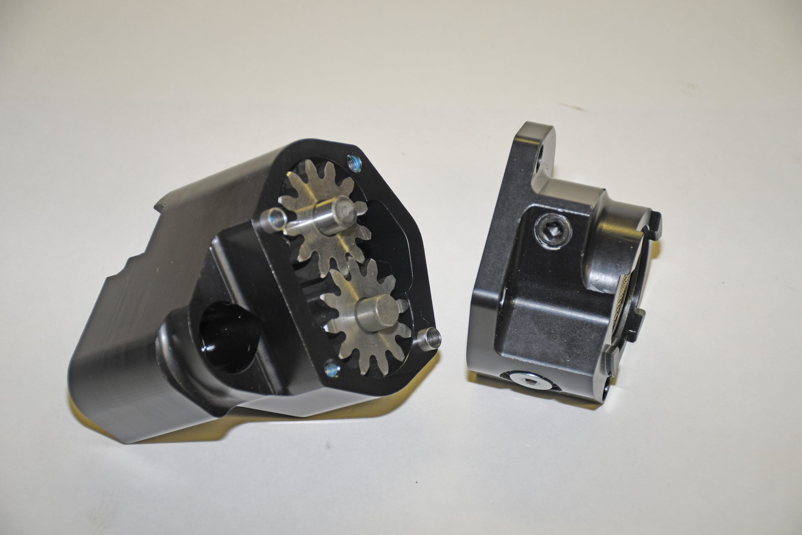
Using a conventional Chevy wet sump oil system as the example, oil is first drawn through the pickup screen into the oil pump. Here, a pair of gears inside the pump pressurize the oil and then it goes through a gallery within the cylinder block that delivers it to the oil filter. Oil is forced through a filtration medium (paper and/or screen) and then it exits into the main oil gallery. At this point, oil is delivered to the main journals along with the cam bearings. Oil flows through a series of drilled passages in the crankshaft and is directed toward the rod bearings. Oil from the main gallery also moves through the lifter galleries where it’s distributed to the valve lifters. In a typical Chevy application oil that is pumped into the lifters is discharged through hollow pushrods. In turn, this pressurized oil lubricates the pushrod tips along with the rocker arms. Oil pumped to the top of the engine than simply runs back over the valve spring as well as the valve stem and eventually drains back into the sump. This arrangement provides a cooling effect for the springs and obviously provides lubrication for the valve stems and valve guides.
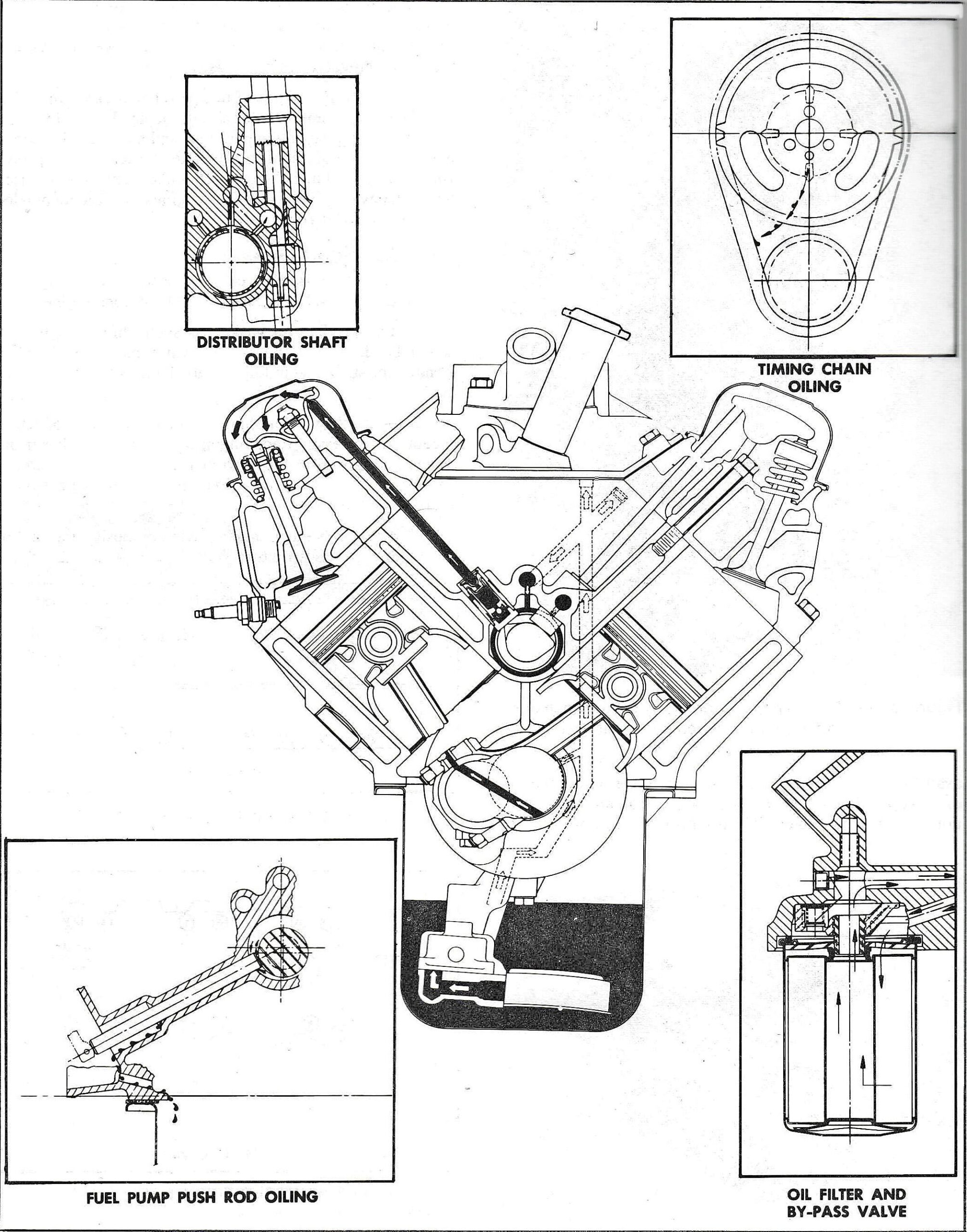
Those aren’t the only pieces lubricated and cooled by oil spray or by way of splash lubrication. Many engine components are lubricated and cooled by oil splash or spray. For example, oil flung off the spinning crank and cam assembly is used to lubricate the cylinder walls, pistons, piston pins, camshaft lobes, distributor gear and timing chain. This oil spray is important and we’ll get it a bit further down the page.
Oil pressure in the range of 30 or 40 pounds per square inch (PSI) is often sufficient in order to maintain proper engine lubrication in a passenger car engine. In contrast, a high performance or race engine application places considerably higher demands and loads on reciprocating components. Increase the operating range (typically past 7,000 RPM in many high performance applications), and the need to increase oil pressure also increases. More pressure is necessary to maintain the separation between the cam and crank journals and the bearings. It’s for this reason one often sees oil pressure figures of 50 to 60 PSI and beyond in race applications. Of course, the design and type of the engine also dictates oil pressure requirements. There are some restricted class cars (for example, some NHRA Stock and some NHRA Super Stock classes) where reduced oil pressure coupled with very thin oil and/or the reduction of oil within the sump is used to increase horsepower. This of course, isn’t without consequences. Ultimately, durability suffers. But for the most part, the oil flow rate in high performance applications typically ranges from 8 to 12 gallons per minute. The oil pump you chose must be capable of maintaining pressure at this flow rate in order to avoid bearing to journal contact. Once a bearing and a journal come in contact with each other, we all know it’s pretty much over and you’re faced with the dismal prospect of engine failure.
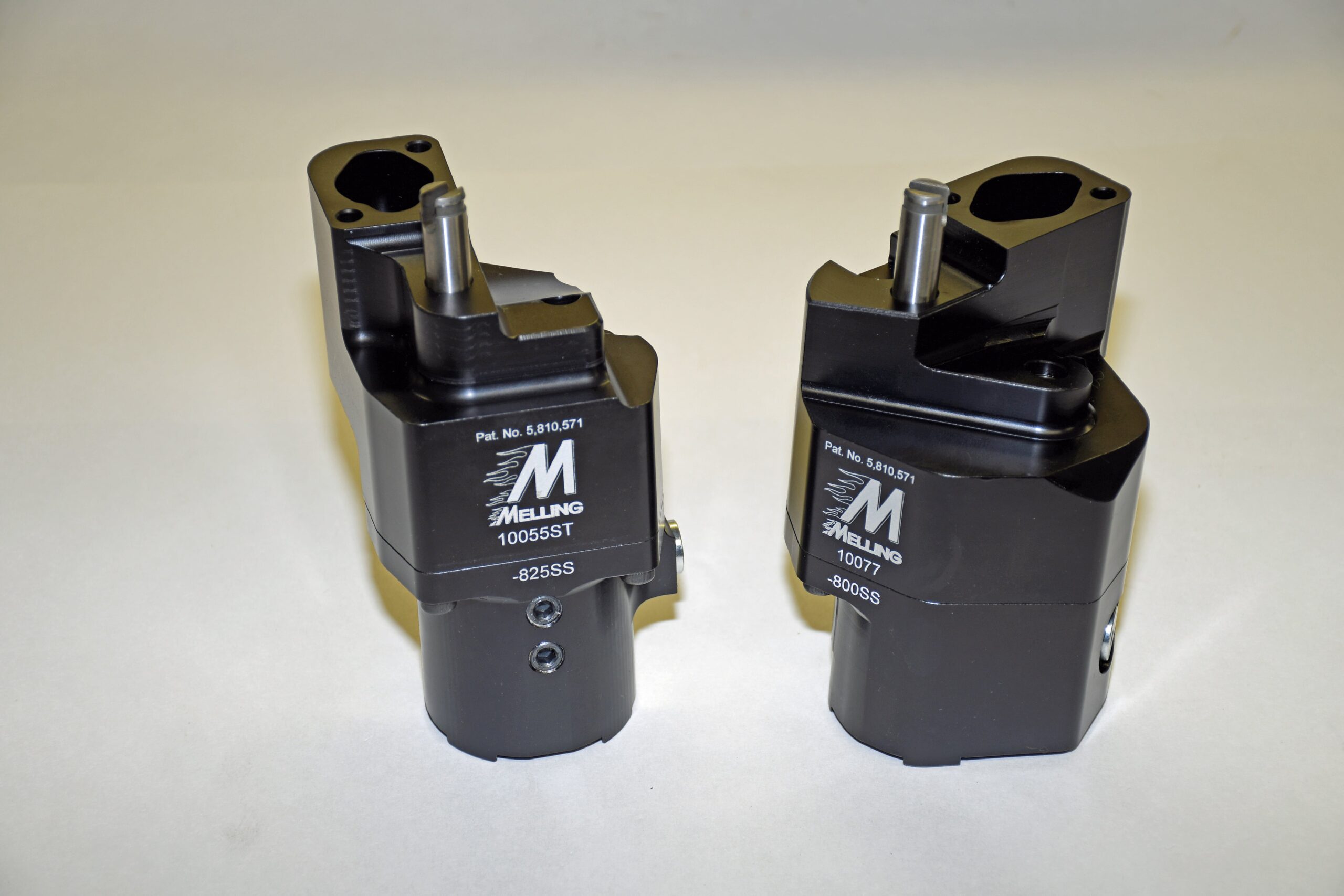
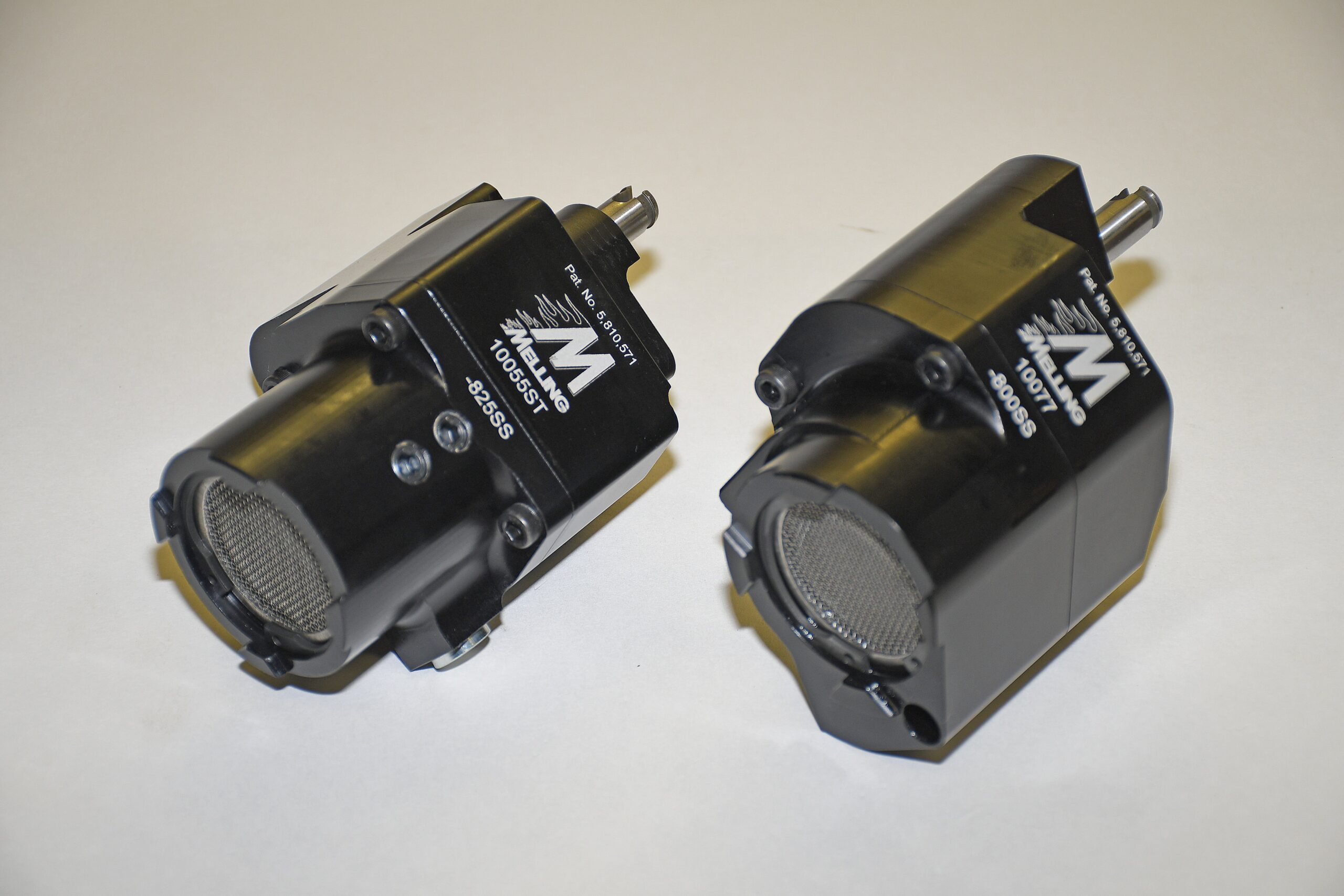
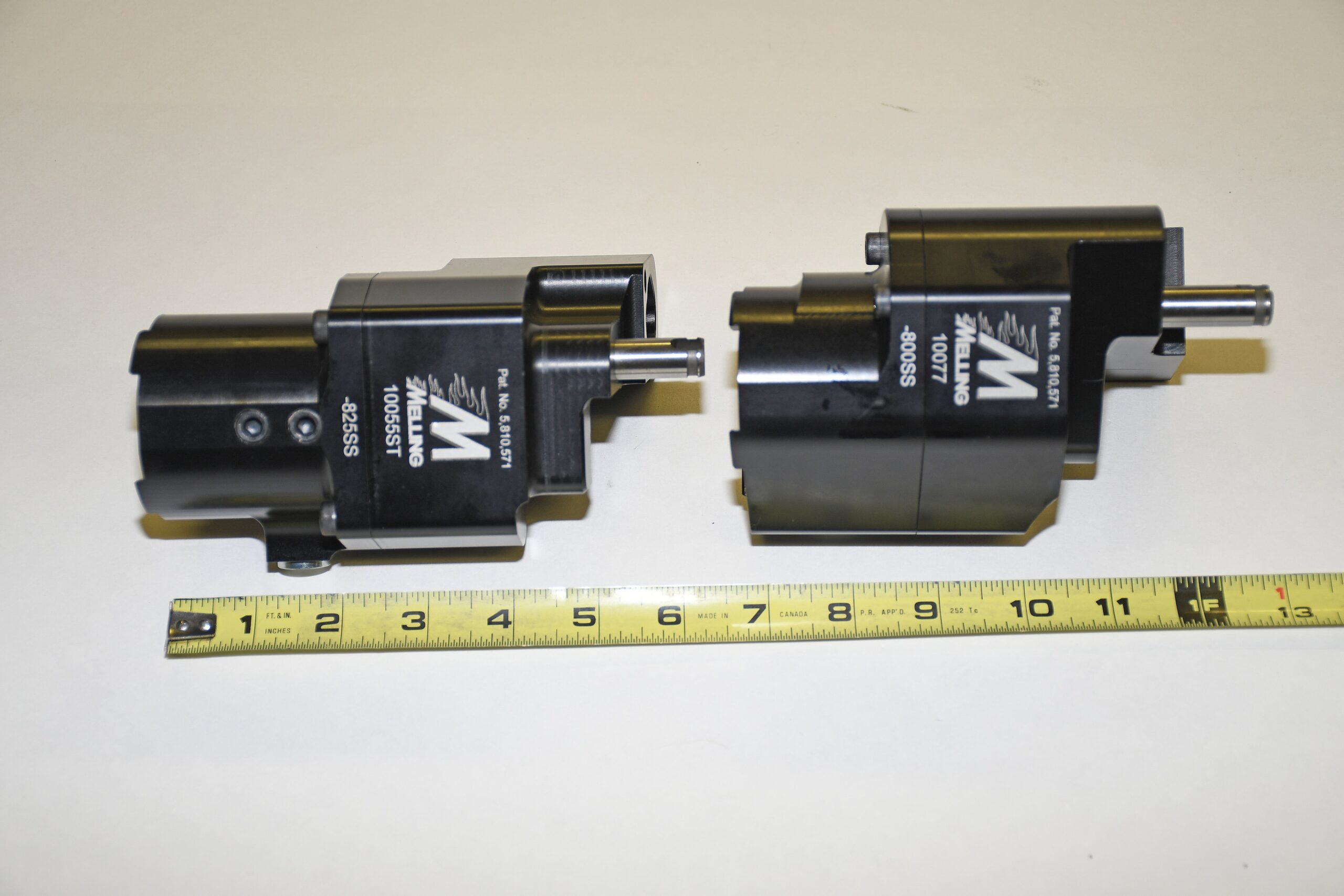
Fair enough. There are ways to resolve this. But you can go too far and we’ll get into it in the next issue. Watch for it. And the meantime, check out the following examples of new oil pump technology from the folks at Melling .
Let’s start at the beginning. The cam, main and rod bearings inside an engine are very simple devices. The most common arrangement we typically see consist of flat, coated inserts. Bearing inserts have zero moving parts (in contrast to a ball bearing or a roller-type bearing you might find in a two stroke engine). Automotive bearings simply rely upon hydro-dynamic principles.
What this means is the crankshaft journals (or the camshaft journals for that matter) do not actually rotate directly on the bearing surfaces. Instead, they rotate on a wedge of pressurized oil. In order to create that “wedge”, oil must first be pumped into the bearing with sufficient force and sufficient quantity to physically lift the journal off the bearing surface. As the crankshaft is rotating, that hydro-dynamic wedge of oil that was created, follows the journal. This prevents the metal journal surface from touching the bearing surface. Basically, the crank and cam journals spin on a cushion of oil.
Using a conventional Chevy wet sump oil system as the example, oil is first drawn through the pickup screen into the oil pump. Here, a pair of gears inside the pump pressurize the oil and then it goes through a gallery within the cylinder block that delivers it to the oil filter. Oil is forced through a filtration medium (paper and/or screen) and then it exits into the main oil gallery. At this point, oil is delivered to the main journals along with the cam bearings. Oil flows through a series of drilled passages in the crankshaft and is directed toward the rod bearings. Oil from the main gallery also moves through the lifter galleries where it’s distributed to the valve lifters. In a typical Chevy application oil that is pumped into the lifters is discharged through hollow pushrods. In turn, this pressurized oil lubricates the pushrod tips along with the rocker arms. Oil pumped to the top of the engine than simply runs back over the valve spring as well as the valve stem and eventually drains back into the sump. This arrangement provides a cooling effect for the springs and obviously provides lubrication for the valve stems and valve guides.
Those aren’t the only pieces lubricated and cooled by oil spray or by way of splash lubrication. Many engine components are lubricated and cooled by oil splash or spray. For example, oil flung off the spinning crank and cam assembly is used to lubricate the cylinder walls, pistons, piston pins, camshaft lobes, distributor gear and timing chain. This oil spray is important and we’ll get it a bit further down the page.
Oil pressure in the range of 30 or 40 pounds per square inch (PSI) is often sufficient in order to maintain proper engine lubrication in a passenger car engine. In contrast, a high performance or race engine application places considerably higher demands and loads on reciprocating components. Increase the operating range (typically past 7,000 RPM in many high performance applications), and the need to increase oil pressure also increases. More pressure is necessary to maintain the separation between the cam and crank journals and the bearings. It’s for this reason one often sees oil pressure figures of 50 to 60 PSI and beyond in race applications. Of course, the design and type of the engine also dictates oil pressure requirements. There are some restricted class cars (for example, some NHRA Stock and some NHRA Super Stock classes) where reduced oil pressure coupled with very thin oil and/or the reduction of oil within the sump is used to increase horsepower. This of course, isn’t without consequences. Ultimately, durability suffers. But for the most part, the oil flow rate in high performance applications typically ranges from 8 to 12 gallons per minute. The oil pump you chose must be capable of maintaining pressure at this flow rate in order to avoid bearing to journal contact. Once a bearing and a journal come in contact with each other, we all know it’s pretty much over and you’re faced with the dismal prospect of engine failure.
Fair enough. There are ways to resolve this. But you can go too far and we’ll get into it in the next issue. Watch for it. And the meantime, check out the following examples of new oil pump technology from the folks at Melling .
Leave a Reply