Click Here to Begin Slideshow
You can do things to a solid axle rear-end suspension to make it handle better than stock. The installation of a multi-link suspension and coilover shocks is the primary thing most owners of solid axle-equipped cars do. Until recently, it gave you the most bang for your buck. However, with just a little more work (and less welding), you can have a modern state-of-the-art independent rear suspension with coilovers. We took a look at what it takes to install the Heidts Hot Rod & Muscle Car Parts Pro G Independent Rear Suspension kit for 1964 ½ - 1970 Mustangs.
You can do things to a solid axle rear-end suspension to make it handle better than stock. The installation of a multi-link suspension and coilover shocks is the primary thing most owners of solid axle-equipped cars do. Until recently, it gave you the most bang for your buck. However, with just a little more work (and less welding), you can have a modern state-of-the-art independent rear suspension with coilovers. We took a look at what it takes to install the Heidts Hot Rod & Muscle Car Parts Pro G Independent Rear Suspension kit for 1964 ½ - 1970 Mustangs.
You’ll Need a Full Toolbox for This Project
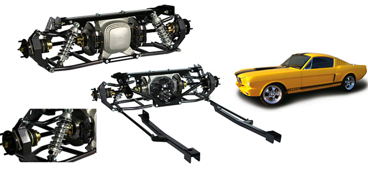
Above: The 64-70 Mustang Pro-G IRS from Heidts.
Other than being confident in your ability to weld - and welding is optional - installing the 64-70 Mustang Pro-G IRS (High Horsepower model) Part Number IRM-101-K from Heidts is fairly easy and straightforward. Although not absolutely necessary, someone else’s help will make the project quite a bit easier. Some tools needed that are a bit out of the ordinary are Allen head sockets, a plastic dead-blow hammer, a torque wrench that can measure inch-pounds and welding accoutrements. If you have access to one, a pneumatic or electric impact gun will make things go a little more quickly and easily.
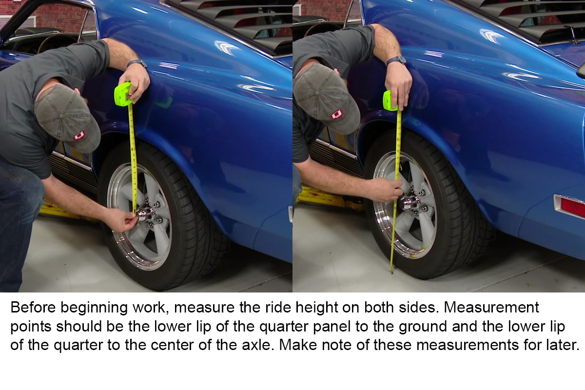
Measure and Record Ride Height Before Lifting Car
Getting this measurement will greatly assist you in setting the car’s ride height after installing the rear-end - something you need to do in order to accurately set the rear alignment after installation. Once you’ve written it down for both sides, you can lift the rear of the car under the differential. Block the front wheels and place jack stands under the rear frame rails, in front of the leafspring mounts. Lower the car onto the stands and leave the jack supporting the differential. Liberally spray the front and rear leafspring mounts with penetrating oil.
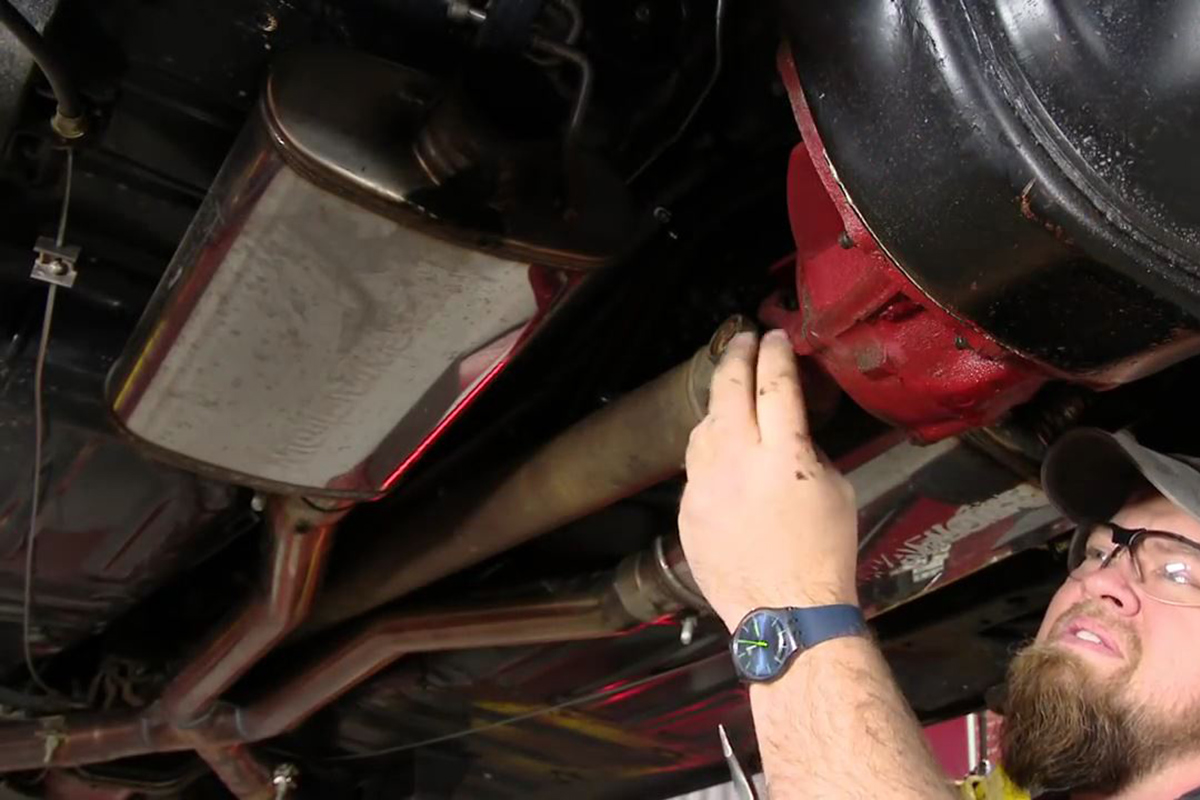
Remove Driveshaft and Exhaust
Your stock exhaust isn’t going to work after you install the new IRS – plus, it’s in the way of installing the new suspension. You’ll need to replace the exhaust from in front of the axle to where it exits under the bumper with the exhaust from a newer Mustang with IRS. The driveshaft has to come out because it’s connected to the rear-end’s third member. Four bolts secure the driveshaft to the pinion yoke.
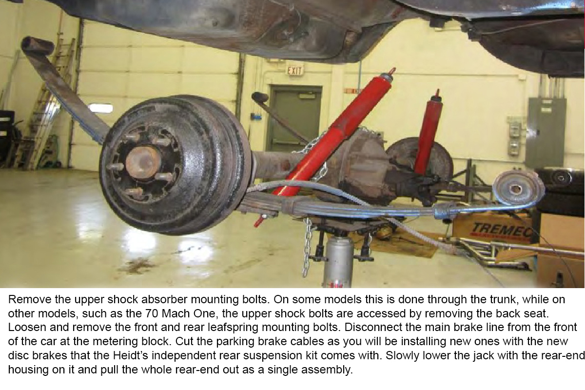
Remove the Rear-End as an Assembly
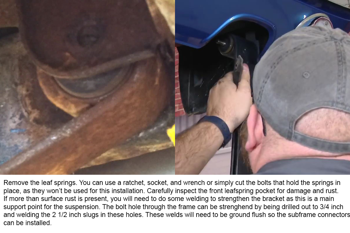
Three nuts and bolts secure the leafsaprings in the car. One bolt is located at the front and two, one above the other, are located at the back of the car. Although it looks like you can remove the lower bolt at the rear and release the leafspring, it’s makes things easier to remove both bolts.
Safety Note
Especially when working with jack stands, some people will place a wood board under the differential and tie the differential to the jack. Prior to cutting the parking brake cables, make sure the kit you purchased has the parking brake option.
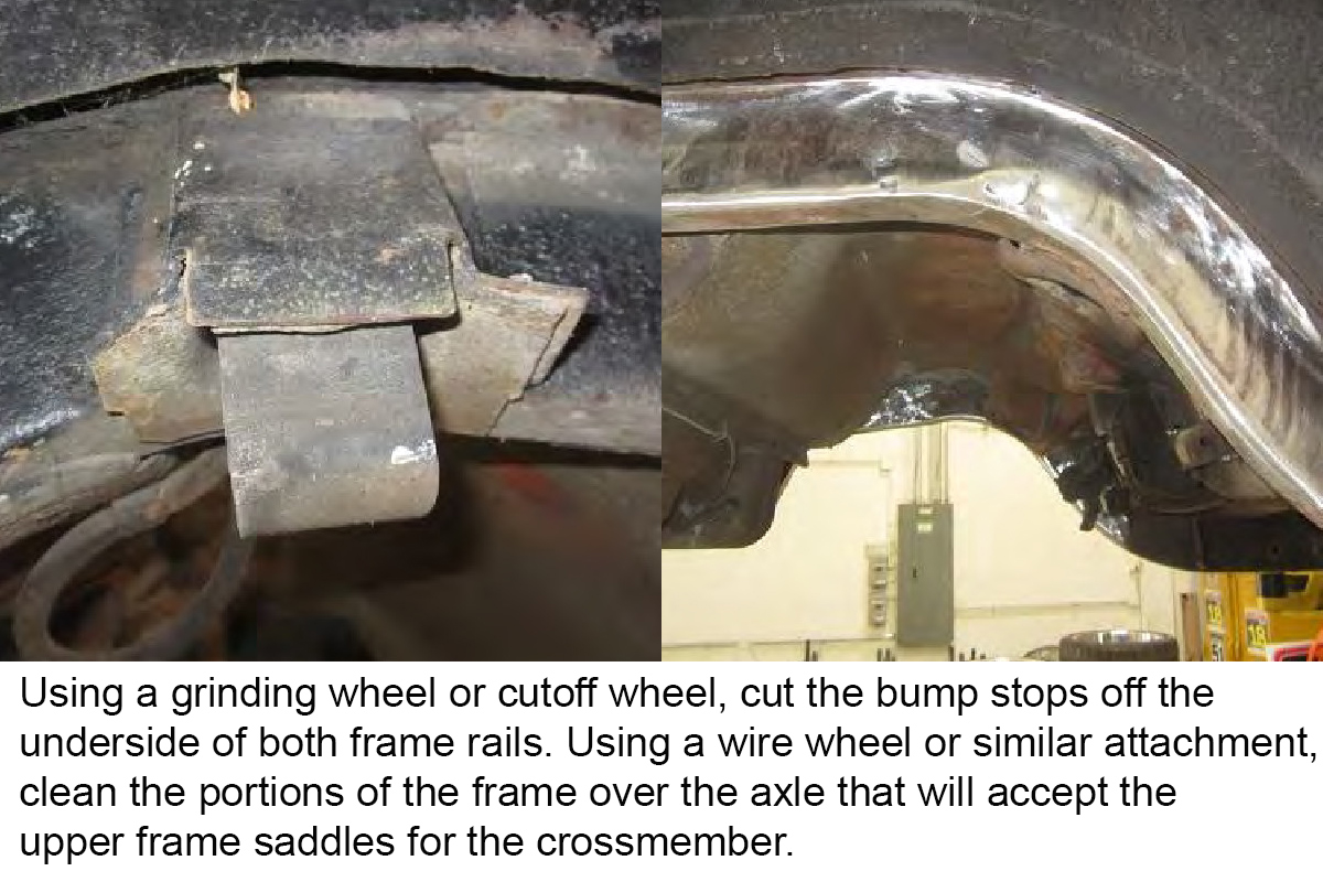
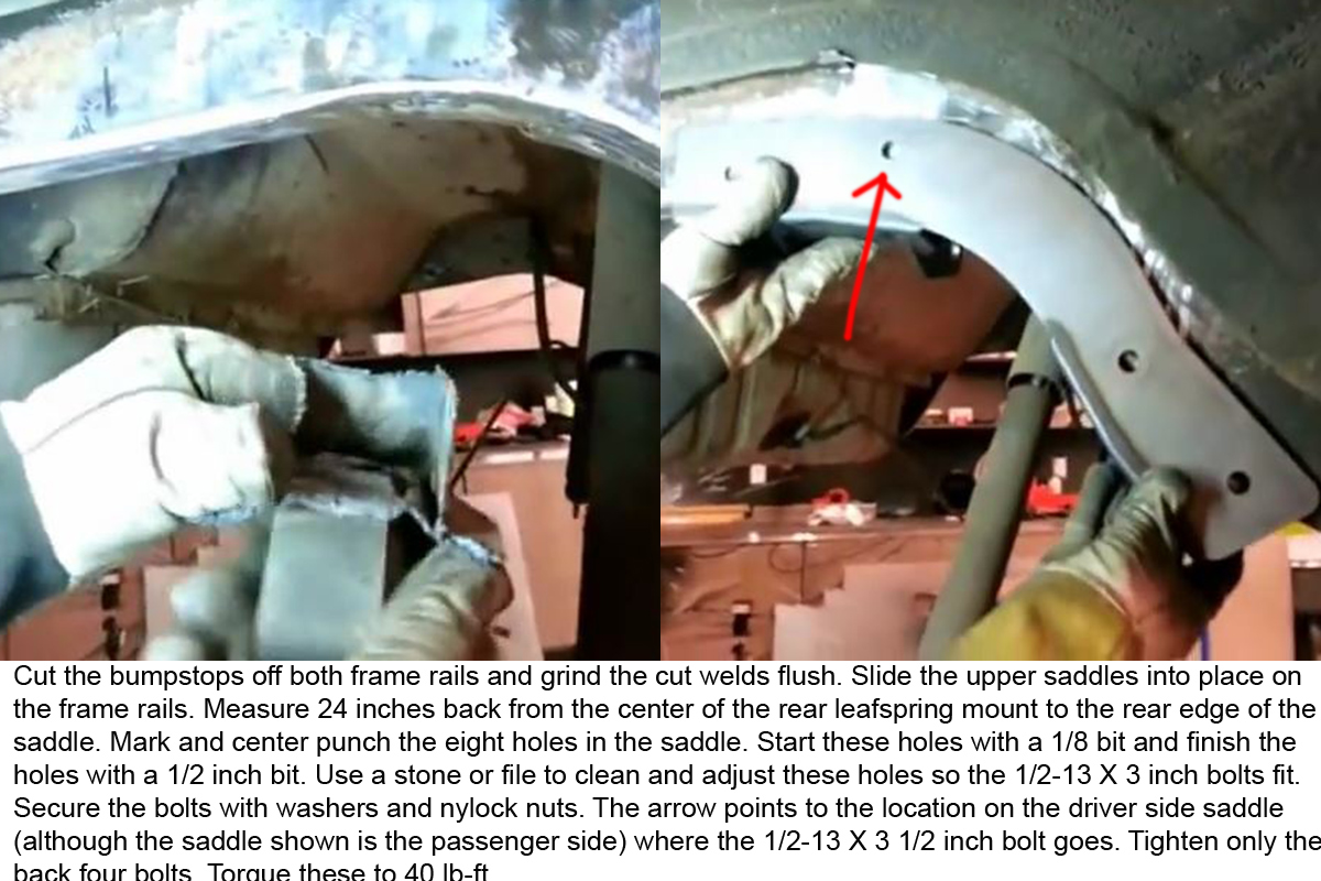
Prep the Frame for Crossmember Saddle Installation
This step is required because the bump stop and normal buildup on the frame rails will keep them from sitting properly. You need to make sure that the area where the bump stop was welded to the frame is smooth. Also, make sure the rails aren’t dented or bowed outward or rusted through. Repair as required before moving on.
Place Crossmember Saddles on Frame Rails
The crossmember saddles are side specific. When installed correctly, the crossmember mount is almost centered in the wheel well. Use the dead blow hammer to fully seat the front, but leave the rear ¼-1/2 and inch from the rail at the rear. This will let you adjust the positioning of the saddle more easily.
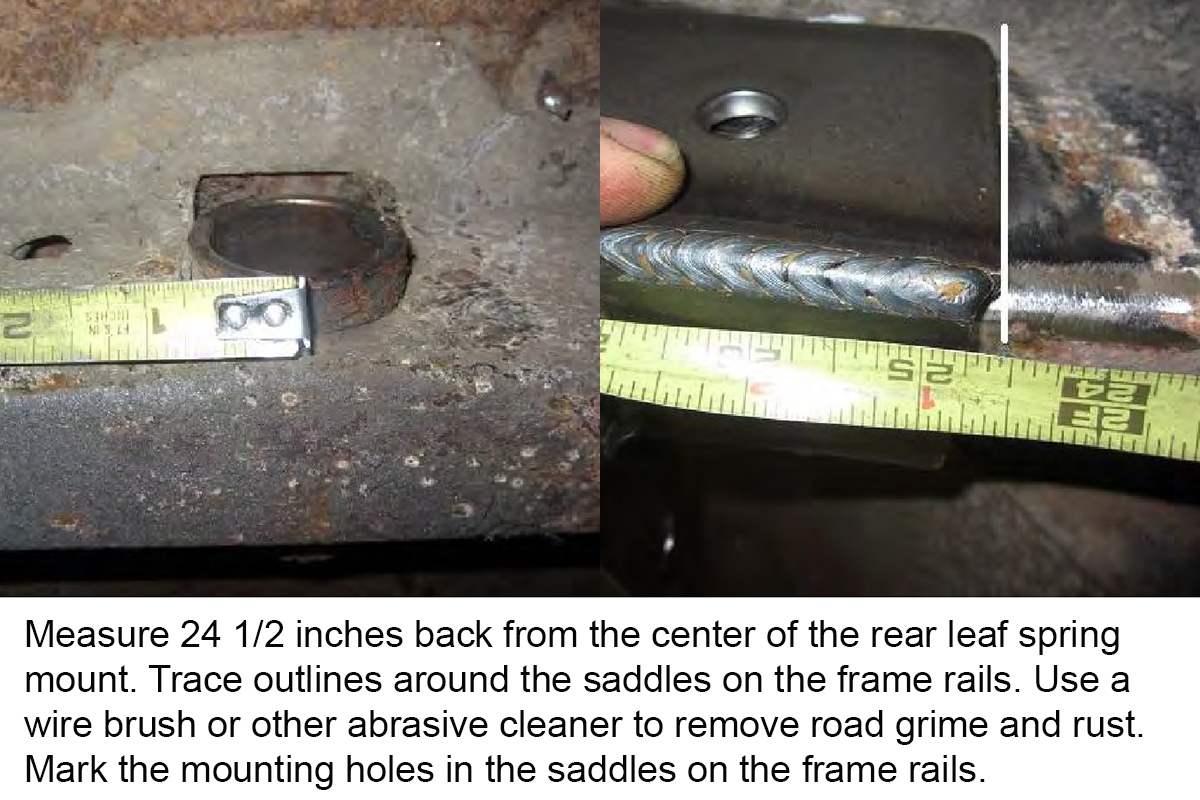
Properly Position Saddles on Frame Rails
Clean an area along the side and top of the bracket and the frame rail to ½ inch from the bracket. Using a half inch punch with a pointed tip makes getting the exact center of the holes that need to be drilled easier. It’ll also help keep the 1/8 bit from drifting.
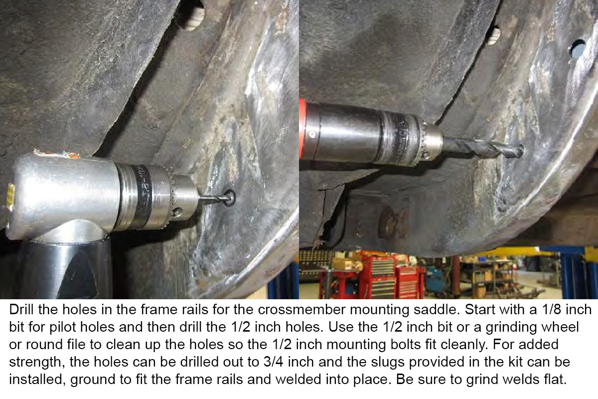
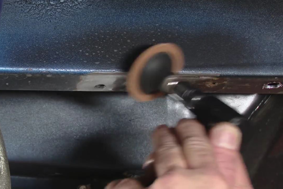
Drill Holes for Saddles
Removing the saddles to drill the frame rails isn’t required, but it keeps you from damaging the mounting holes. Drilling a pilot hole isn’t required if you have a unibit/stepper bit. If you choose to drill these holes out to ¾ inch and insert the slugs for extra strength, make sure you grind them down to flush with the frame rail and at least solidly tack them in place, grinding those welds smooth.
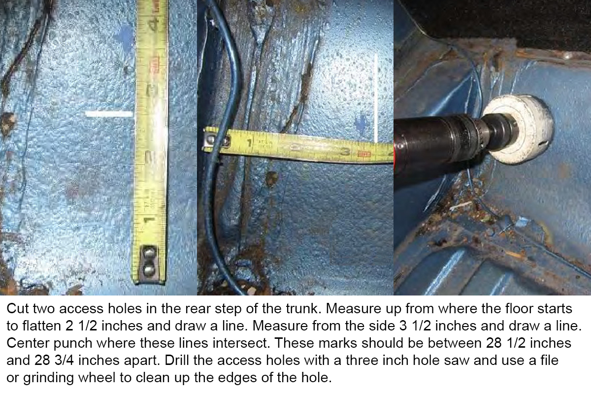
Drill Access Holes in Trunk
Unless you drill access holes in the trunk, you won’t be able to install the crossmember and upper shock mount bolts.
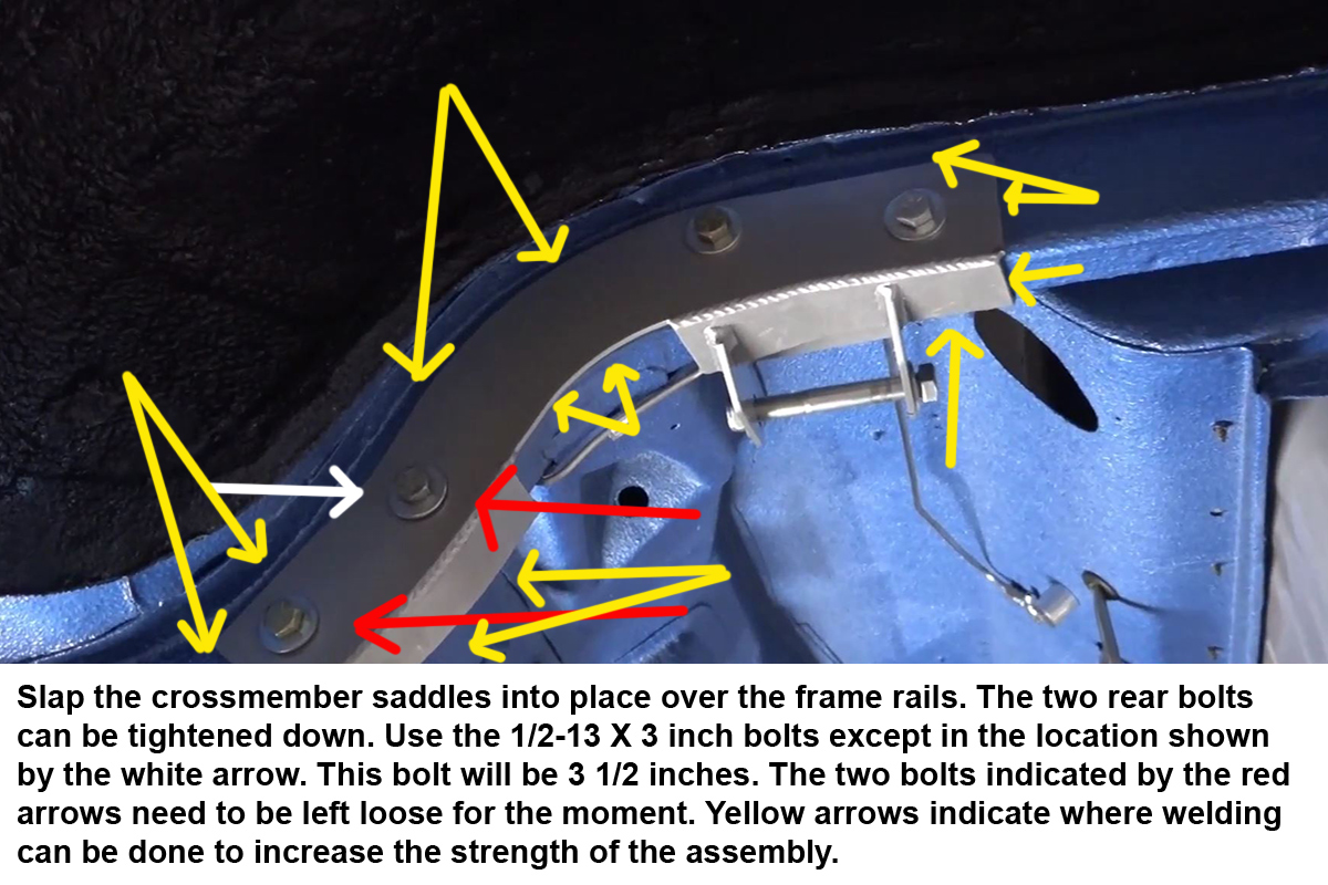
Install the Saddles
Using a regular metal hammer to position the saddles can cause damage to the saddles. Using a soft-faced dead blow hammer precludes this. The two rear bolts should be torqued to 50 lb-ft.
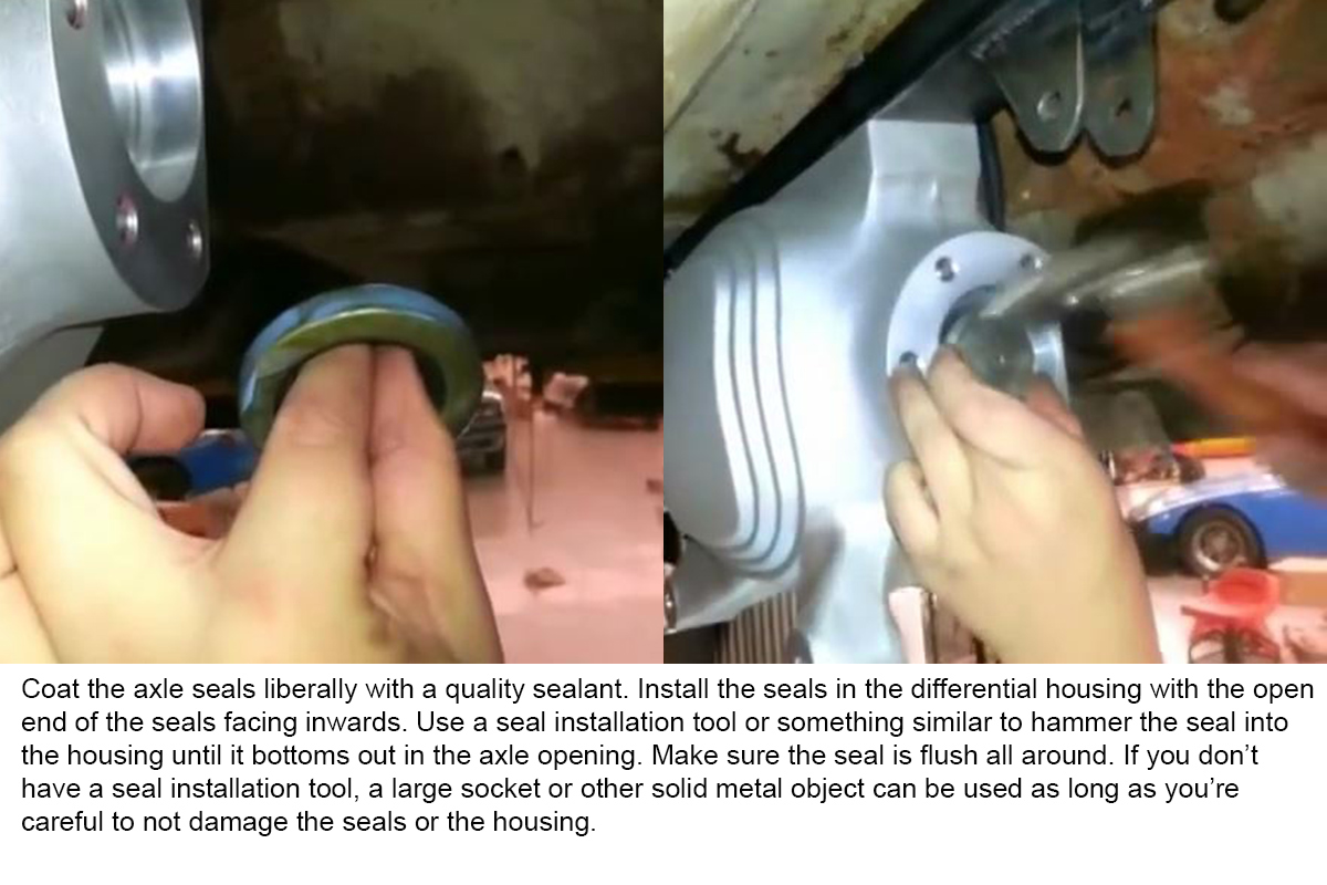
Install Axle Seals
Axle seals keep the gear oil from leaking out around the stub axles. They also help center the stub axles during installation. Using a light film of sealant around the outer circumference of the seal helps ensure it seals to the housing and makes installation a little easier. You should install the seal evenly. Some sort of installation tool makes installing the seals much easier, because the housing is recessed.
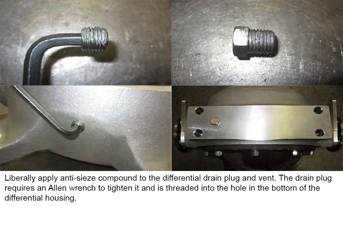
Install Drain Plug and Vent
Neither of these has a set torque specification. They just need to be tight enough to keep the gear oil from leaking out and keep the plugs from loosening due to road vibrations.
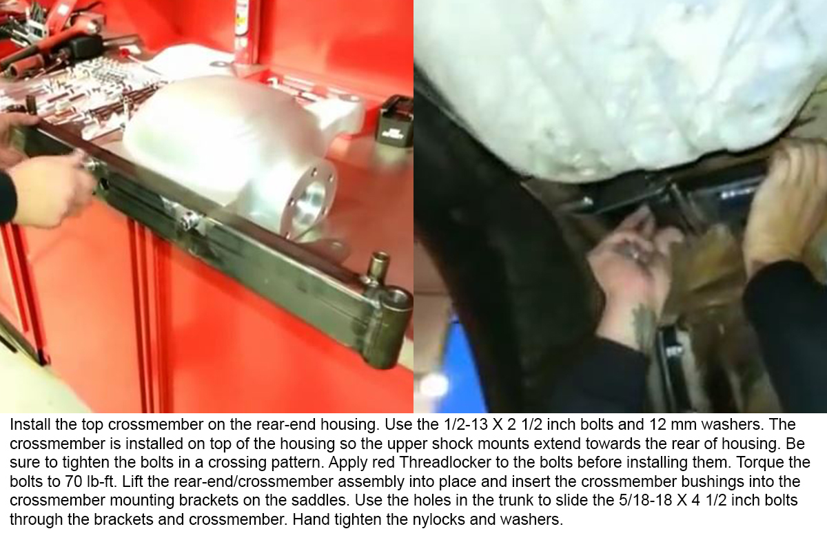
Install the Crossmember/Rear-End Housing Assembly
After finishing this step, your friend can take a break. If you’re by yourself, you can tie the rear-end assembly to your jack and use the jack to lift it into position.
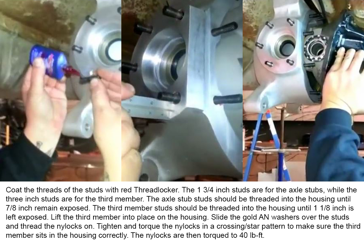
Install Studs and Third Member
If the kit you ordered didn’t come with a third member assembly and you haven’t otherwise purchased one, you’ll need to use the third member from the original rear-end. Make sure you run a thin bead of sealant on both sides of the gasket before installing the third member.
Install the Pinion Support Plate
Don’t knock the pinion support loose while you have the bolts out installing the pinion support plate. This plate helps control rotational forces. The bolts provided with the IRS installation kit must be used.
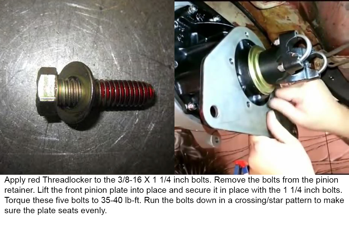
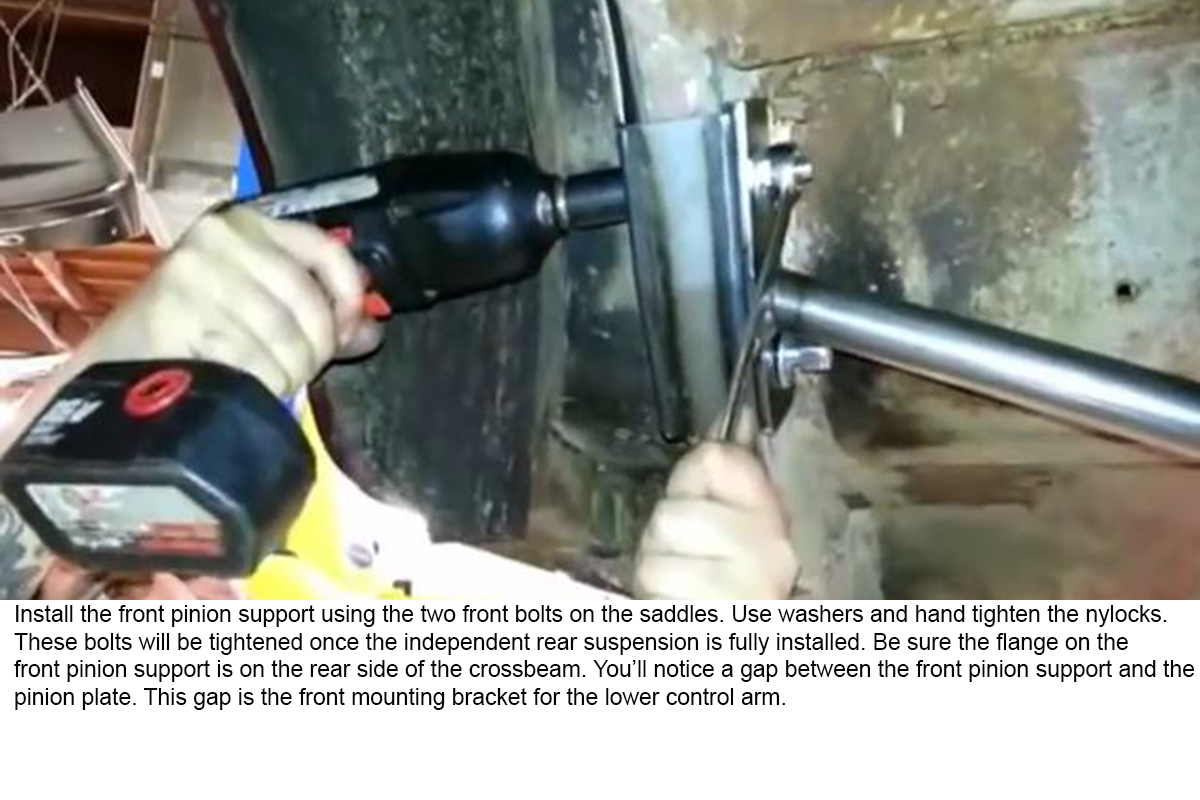
Install the Front Pinion Support Bracket
This helps give the rear-end some stiffness while under heavy torque and high load. There is no torque spec for these bolts other than “tight.” Install the driveshaft during this step as well.
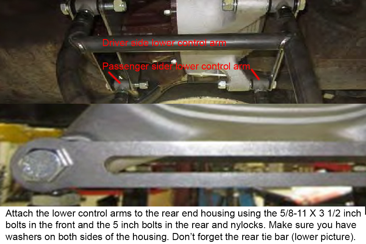
Install the Lower Control Arms
A friend’s help here can be handy, but it isn’t necessary. Make sure you put the correct control arm on the correct side, and orient them correctly. Don’t tighten the jam nuts on the adjusters until after you do the alignment.
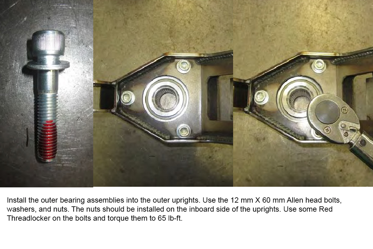
Install the Outer Hubs
The three bolts for the hub and bearing must be installed from the backside of the control arm upright. Snug all three bolts before torqueing.
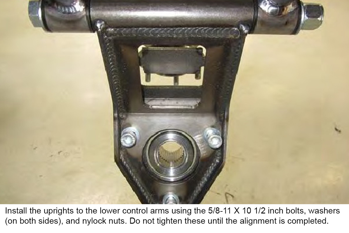
Install the Outer Uprights
The outer uprights should be installed so that the bolt heads are towards the center of the car when the lower control arms are raised into position. Again, the two bolts can’t tightened until the alignment has been done.
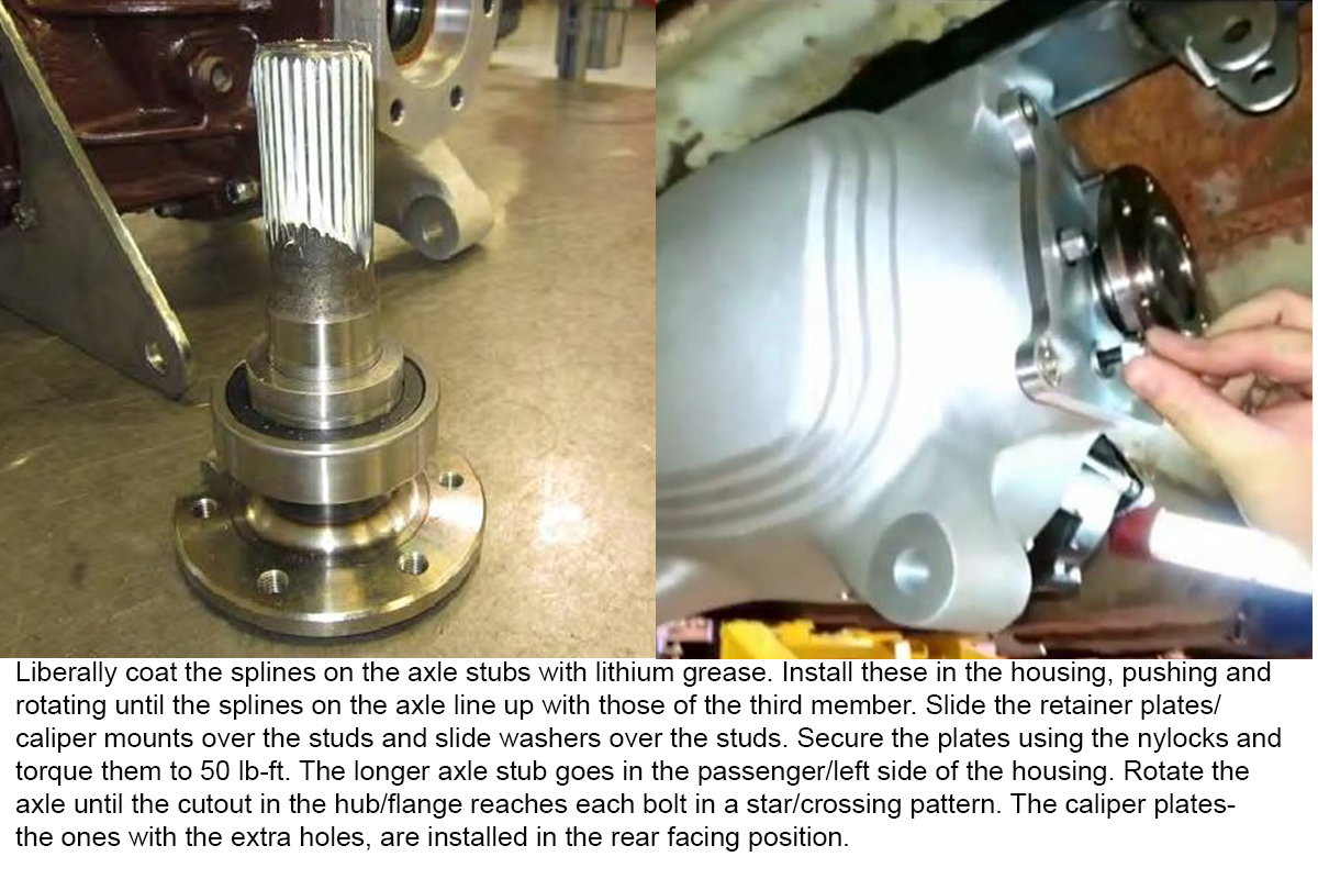
Install Stub Axles
The stub axles are installed in the rear-end housing next. Be sure to liberally coat the splines with lithium grease to ease their installation. Also, make sure they bottom out completely when installing them. The two rear axle retainer plates double as the caliper mounting bolts. You can now fill the differential with your choice of gear oil.
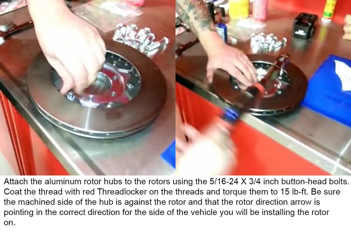
Assemble Rotors and Hubs
Because the bolt pattern on the inner CV joint is different from that of a car’s wheel, the rotors require an adapter hub for installation. This hub is then sandwiched between inner joint and the axle stub hub. Be sure to double- and triple-check your torque wrench setting is in inch-pounds before torqueing the button head bolts.
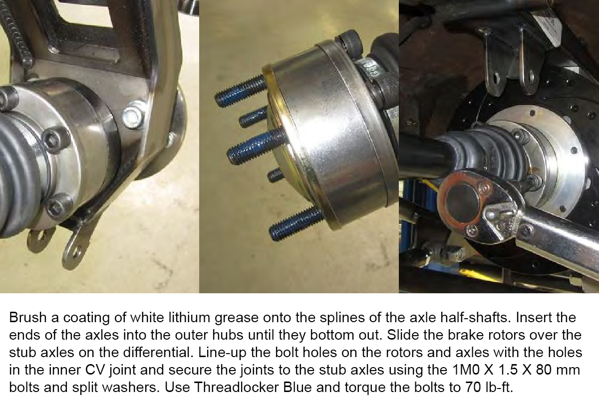
Rotor and Axle Half Shaft Installation
This operation is sometimes more easily accomplished with the help of a friend holding the lower control arm in position as you stab the Allen head bolts through the CV joint, rotor hub and axle stub hub. Be sure when running these bolts down and torqueing them that you do so in a crossing/star pattern.
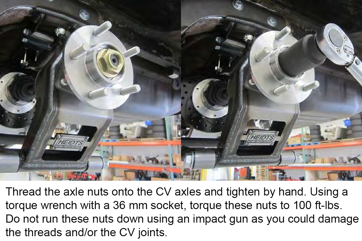
Torque Axle Nut
If you haven’t already, install the driveshaft and put the transmission either in gear or park. 100 ft-lb is an awful lot of torque for you to try and keep the axles from turning against as you torque the axle nuts. You could also try bolting a pipe into the pinion yoke instead of the driveshaft and using the pipe as counter-torque while torqueing the axle nuts.
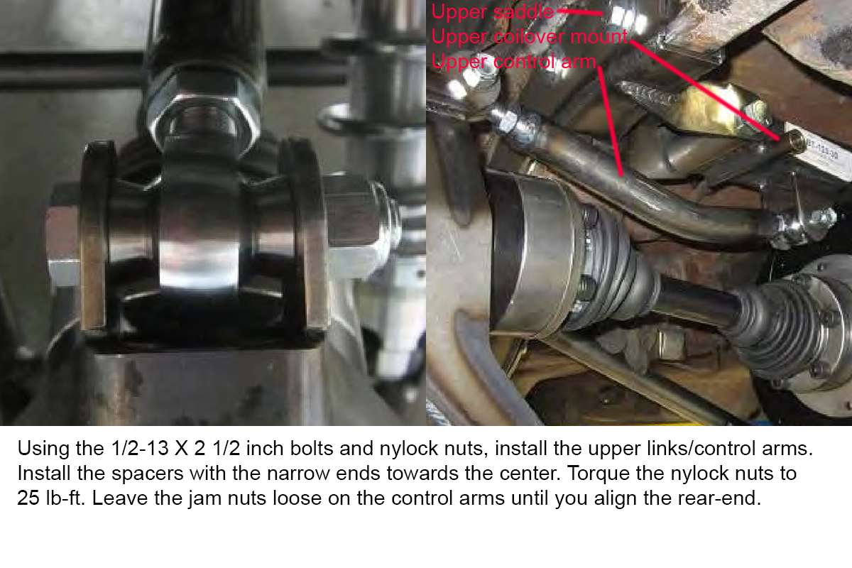
Install Upper Links/Control Arms
The bend in the upper link/control arm is there to help the control arm clear the frame during suspension travel. Be sure the link is oriented so the bend points down.
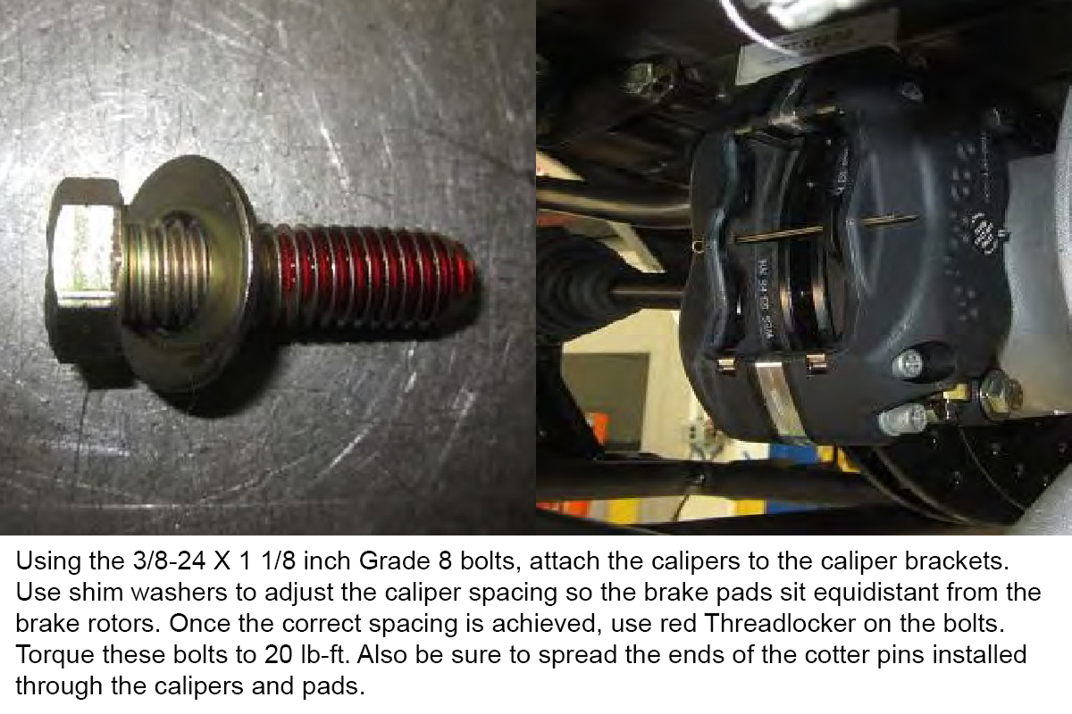
Install Calipers
If your Heidts IRS kit was ordered with the emergency/parking brake option, now is when you’ll want to install it. The calipers have two small hooked arms on them. The ends of the parking brake cable attach to the hooked arm, while the center of the cable is routed to the horseshoe in the center of the car and adjusted.
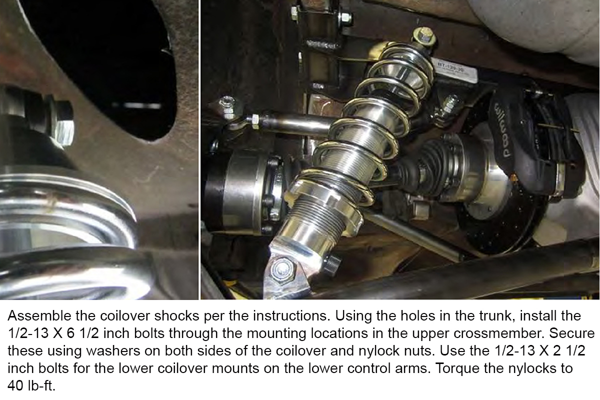
Install Coilovers
Heidts says you should install the coilovers without the coils, but you can’t be sure you have the ride height adjusted into the ballpark without the coils, and you have to remove them to install the coils. Collapse the coils safely and install them on the shocks. Make sure the shocks are installed so that, if so equipped, the adjusting knobs face the center of the car.
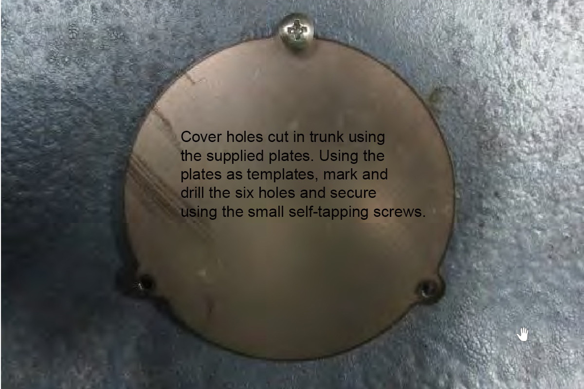
Install Cover Plates Over Access Holes
You don’t want those two unsightly holes in the trunk. The cover plates also help keep road junk and water out of the trunk. If you have it, you should cut a piece of gasket maker material to fit the cover plates. This gives you an added level of protection from water entering the trunk.
Now you can level the IRS in relation to the frame rails. Place a jack under the front pinion support and, using a level between the crossmember and rail, raise one side or the other as needed to level the crossmember to the rails. Once this is completed, tighten all the bolts on the saddles, crossmember and pinion support.
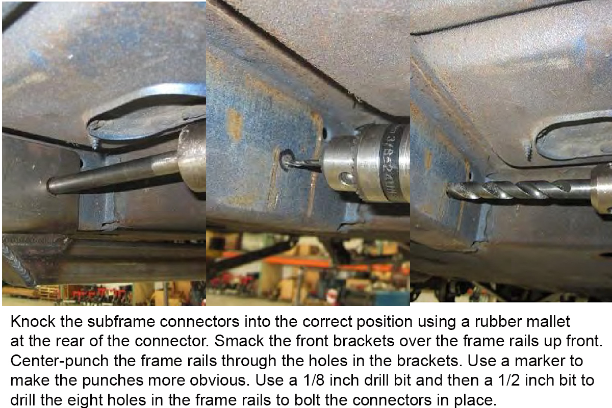
Subframe Connector Installation-Frame Prep
I prefer using a Unibit/stepper bit to drill the ½ inch holes instead of using multiple bits. Just make sure that the punch you use has a good point on it and the bit won’t drift.
For a more detailed look at how to properly install subframe connectors on an older Mustang, see my article on the subject.
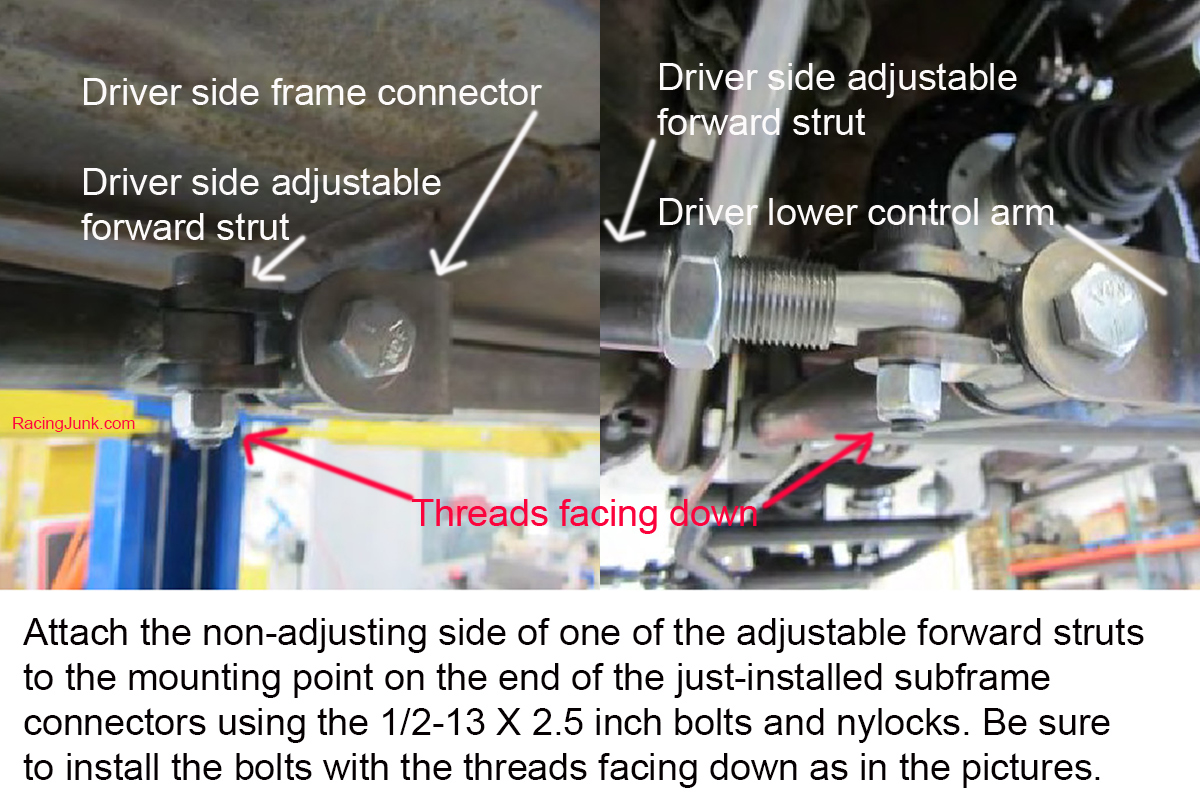
Installing the Lower Forward Adjustable Struts
Other than putting the tires back on and adjusting the suspension, this is the last step of the process.
Set the Rear Ride Height
I like to either lower the wheels onto blocks or lower the control arms on jack stands for this step. If you’ve got a rack or, even better, an alignment rack to do your work on, you can simply lower the rear wheels onto the rack. Rear ride is set by making sure that the rear suspension is loaded exactly like it would be when driving and then adjusting the big spanner nuts on the bottom of the coilovers until the ride height is set to either what you measured in the first steps above, or to the new, lower ride height you’re looking for. Once the ride height is where you want it, lock the spanners with the lock nut and set screws.
Adjusting the Rear Alignment
Adjusting the rear alignment is easier with the wheels off than it is with the wheels on, unless you have an alignment rack with skid plates to allow the wheels to move. Caster should be set to zero. In other words, the two points on the upright where the control arms mount to the upright should be as perfectly lined up on the vertical as you can get them. Caster is adjusted by using the lower forward adjustable rods. Exposing more threads pushes the lower control arm back, and exposing fewer threads pulls it forward. Lock down the jam nut when finished.
You want the camber, the angle off the vertical of the rear uprights, to be as close to zero degrees, vertical, as you can get it. This is adjusted using the adjusters on the upper and lower control arms. Rotating the adjuster sleeve on the upper arm so the arm collapses and fewer threads are visible will pull the upper part of the upright and make the camber angle go negative.
Camber and toe are adjusted using the adjusters on the lower control arms. Turning the front adjuster so more threads are exposed will give more toe-out, while turning the rear adjuster so more threads are exposed gives more toe-in. Toe should be set to zero to 1/16 inch toe-in. When adjusting toe, be sure to turn the two lower adjusters an equal amount in opposite directions. This will cause the effect their adjustment has on camber to be negligible. Once camber and toe are properly set, lock down the jam nuts.
Once you’ve got the car back on the ground, take it out for an increasingly hot test drive. Start slowly and safely so you can react if the suspension does anything funny or unexpected. After about 500 miles, go back and recheck the alignment and ride height and retighten everything.
Mike's love of cars began in the early 1970's when his father started taking him to his Chevron service station. He's done pretty much everything in the automotive aftermarket from gas station island attendant, parts counter, mechanic, and new and used sales. Mike also has experience in the amateur ranks of many of racing's sanctioning bodies.
5 Comments on Installing the Heidts Pro G on a ’64-70 Mustang
For Pete’s sake RJ, Either FIX the problems with your site displaying pictures, or better yet, get rid of this aggravating slideshow format and just write a darned article with some embedded pics.
Thanks for the response.
It’s not just your articles, it’s all of these slideshow galleries on the RJ site.
It will display the first couple pics, then the next ones are blank.
I can usually get them to display by switching to full screen, but then when I advance a few more it does it again, until I switch back out of full screen.
I have the same problem with the galleries in RJ ads.
I run the latest version of Firefox, which works great on most other sites.


![[Gallery] Amelia Island Kickoff Car Show And Concours D"Lemons](https://www.racingjunk.com/news/wp-content/uploads/2026/04/DSC_2847-e1777055210316-376x206.jpg)


For Pete’s sake RJ, Either FIX the problems with your site displaying pictures, or better yet, get rid of this aggravating slideshow format and just write a darned article with some embedded pics.
What’s the issue you’re having with images?
Thanks for the response.
It’s not just your articles, it’s all of these slideshow galleries on the RJ site.
It will display the first couple pics, then the next ones are blank.
I can usually get them to display by switching to full screen, but then when I advance a few more it does it again, until I switch back out of full screen.
I have the same problem with the galleries in RJ ads.
I run the latest version of Firefox, which works great on most other sites.
Ugh – just stick a Mark VIII/ Tbird or even a Jag IRS! Almost straight bolt- on and less headaches!
Looks like a Jag rear with inboard disk brakes. 9″ rear strength with Jag handling would be a huge improvement!