

![[Gallery] 3rd. Annual Father's Day Classic Car Show](https://www.racingjunk.com/news/wp-content/uploads/2026/07/Calistoga-2026-18-scaled-e1783026475349-376x206.jpg)

![[Gallery] Blackhawk Museum Stop Over](https://www.racingjunk.com/news/wp-content/uploads/2026/06/DSC_0918-e1782449621944-376x206.jpg)
Piston Primer Part 4
Click Here to Begin Slideshow
What follows is our final segment dealing with high performance pistons for street and strip applications. Previously, we’ve addressed forgings versus castings, ring lands and groove clearance, and deck and dome surfaces. This time around, we’ll examine wrist pin bores and the area that surrounds them, along with pin clearance, pin oiling and wrist pin retainers. Check it out:
PIN BORES – In the last issue, the section on compression height dealt with the wrist pin vertical dimensions. That’s not the end of story when it comes to the wrist pin area of the piston; you also have to consider the horizontal plane. Wrist pins can be located in the center of the piston skirts or they can be offset. Offsets usually arise when the rod length or the stroke is increased. Most engine builders agree that a centered relationship is the best, but you'll get arguments for both cases.
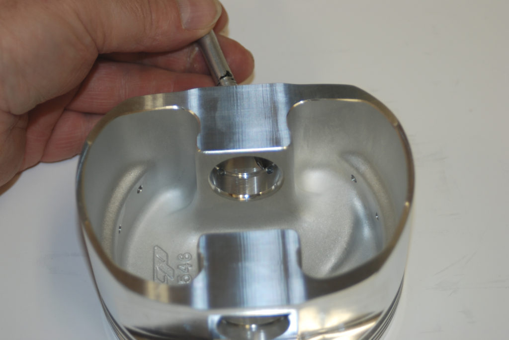
Two things you should think about when looking at custom pistons are the size of the pin supports and wrist pin clearance. Ideally, the pin supports (sometimes called "piers") should be as large as possible. Unfortunately, large pin supports can also increase piston weight. The next best move is to move the supports together. The closer they are, the better the chance of supporting the pin. Remember that there should be adequate side clearance between the supports to allow for "side float" misalignment.
When it comes to pin clearance, most production cast pistons operate with a figure of 0.0002-0.00025-inch. Pistons forged with a high silicon alloy can have a hot running clearance of between 0.0015-0.0020-inch (the cold, installed numbers begin at 0.0002-inch). On the other hand, some engine builders recommend a cold clearance of as much as 0.0008-inch between the pin and the pin bore. Generally speaking, the correct pin to bore clearance figure depends upon the piston type, the form of pin retention and the operational situation. Always double check pin clearance figures with your piston manufacturer.
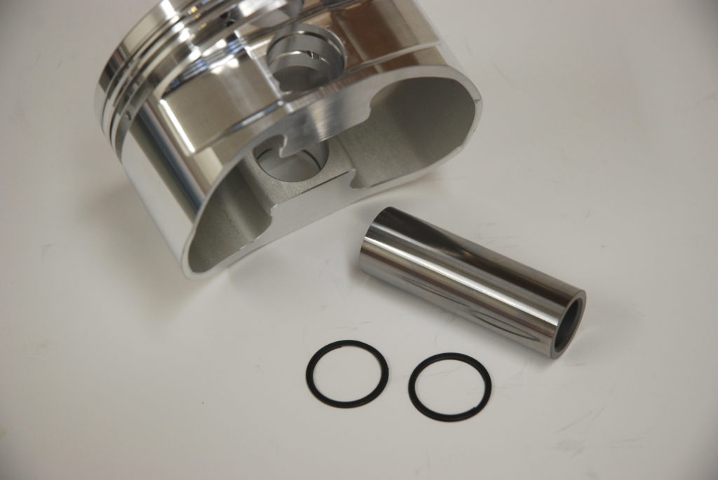
WRIST PIN RETAINERS -- Wrist pins can be held in by two different methods -- pressed in place or floating (with various lock arrangements). A pressed pin, sometimes called a "locked-in-rod" pin, is self-explanatory. The piston, wrist pin and connecting rod are assembled with a press. Basically, the pin can't move because of the interference fit in the connecting rod. It works well (actually very well), but if your application requires teardowns (as in most high performance cars), it's a pain to take the rod-pin-piston package to a machine shop for disassembly and re-assembly. One thing to remember, though, is the fact that there is virtually no horsepower loss when you use pressed pins.
On the other hand, floating wrist pins are more convenient, but add another problem: The pin locks must stay in place until you decide to remove them. Otherwise, you'll have major carnage inside your engine. Typically, performance pistons are machined for one of three (or four) possible pin lock systems: Tru-Arcs, Spiro Locks (or wire retainers) or buttons. Pin buttons are the least common, and in most cases they're only found on fuel and blown alcohol drag race engine combinations. On the other hand, performance pistons will often feature Tru-Arc retention. Tru-Arcs are basically circlip devices that can easily be installed with a pair of snap ring pliers. Spiro Locks are another matter entirely. A Spiro Lock is basically a spiral clip that is "wound" into the retainer groove. It is almost impossible for a Spiro Lock to back out in a running engine, but it is also more difficult to remove when you're working on the powerplant (there are special tools available, but according to CP Carrillo, you simply insert a thin blade screwdriver into each notch of the Spiro Lock, then lift the lock end out of the groove and remove it by threading it outward in a circular, clockwise motion).
Most high performance pistons will be machined for double Tru-Arcs or a Spiro Lock set up. The thinking behind double Tru-Arcs is that a pair of retainers on each end of the wrist pin is less likely to fall out than a lone lock. When using double Tru-Arcs, always snap the pair of locks into the groove with the rounded edges facing each other. If a single Tru-Arc is used, always install it with the rounded edge facing the wrist pin. In addition, Tru-Arcs and Spiro Locks should never be re-used after the engine is disassembled. The clips lose tension every time you compress them with pliers. Finally, purchase your new retainers from the piston manufacturer. Many piston wrist pin sizes are custom and so are the locks (and grooves which hold them in place).
PIN OILING – There are a number of methods used to oil the wrist pin. The simplest form is based upon the "splash" system: A hole is simply drilled at the bottom end of the pin boss, visible from the base of the piston. As the crankshaft spins, oil splashes upward, enters the hole and lubricates the pin. In pistons with this type of pin oiler, there is always a chance that oil didn't "splash" into the hole and lube the pin. And as you can well imagine, there is no real way to regulate the volume of oil that reaches the pin.
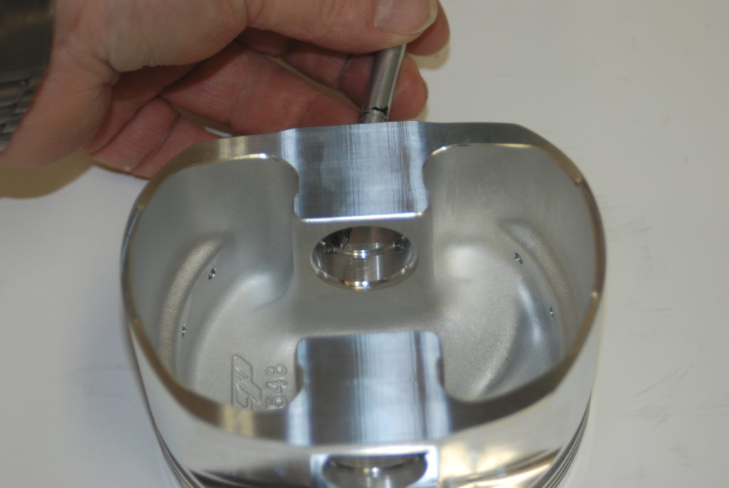
Pressure oiling is very common in high performance and racing pistons. A passage is drilled from the oil ring groove to the top of the wrist pin bore. As the oil is scraped from the cylinder wall, it's directed to the pin oiler and then on to the wrist pin. This is a very efficient system, and as the piston speed increases, so does the oil pressure to the wrist pin. CP Carrillo takes this pressurized pin oiling setup one step further – they actually incorporate a pair of pin oilers on each side of the pin boss, effectively doubling the amount of oil to the wrist pin.
Another pin oiler design you might encounter uses a bit of both of the above concepts, with some modifications. A hole is drilled horizontally from the oil ring groove to the inside of the piston, over the wrist pin. One or two holes are drilled from the bottom of the boss to the pin (similarly to the "splash" system). In addition, two oiling grooves are milled into the pin bore, running horizontally over the pin. Pressurized oil is fed by the oil ring "oiler" to the inside of the piston, where it sprays the wrist pin. The oiling grooves carry the lubricant over and around the pin (inside the boss).
Which system is best? That's up to you, but always remember that a pressure-fed system is far superior to one that relies upon oil splash for lubrication.
###
For a closer look at many of the above features, see the accompanying photos. When all is said and done, when you’re shopping for pistons for your street and strip machine, spend time examining the pistons. They’re definitely critical mass.
What follows is our final segment dealing with high performance pistons for street and strip applications. Previously, we’ve addressed forgings versus castings, ring lands and groove clearance, and deck and dome surfaces. This time around, we’ll examine wrist pin bores and the area that surrounds them, along with pin clearance, pin oiling and wrist pin retainers. Check it out:
PIN BORES – In the last issue, the section on compression height dealt with the wrist pin vertical dimensions. That’s not the end of story when it comes to the wrist pin area of the piston; you also have to consider the horizontal plane. Wrist pins can be located in the center of the piston skirts or they can be offset. Offsets usually arise when the rod length or the stroke is increased. Most engine builders agree that a centered relationship is the best, but you'll get arguments for both cases.
Two things you should think about when looking at custom pistons are the size of the pin supports and wrist pin clearance. Ideally, the pin supports (sometimes called "piers") should be as large as possible. Unfortunately, large pin supports can also increase piston weight. The next best move is to move the supports together. The closer they are, the better the chance of supporting the pin. Remember that there should be adequate side clearance between the supports to allow for "side float" misalignment.
When it comes to pin clearance, most production cast pistons operate with a figure of 0.0002-0.00025-inch. Pistons forged with a high silicon alloy can have a hot running clearance of between 0.0015-0.0020-inch (the cold, installed numbers begin at 0.0002-inch). On the other hand, some engine builders recommend a cold clearance of as much as 0.0008-inch between the pin and the pin bore. Generally speaking, the correct pin to bore clearance figure depends upon the piston type, the form of pin retention and the operational situation. Always double check pin clearance figures with your piston manufacturer.
WRIST PIN RETAINERS -- Wrist pins can be held in by two different methods -- pressed in place or floating (with various lock arrangements). A pressed pin, sometimes called a "locked-in-rod" pin, is self-explanatory. The piston, wrist pin and connecting rod are assembled with a press. Basically, the pin can't move because of the interference fit in the connecting rod. It works well (actually very well), but if your application requires teardowns (as in most high performance cars), it's a pain to take the rod-pin-piston package to a machine shop for disassembly and re-assembly. One thing to remember, though, is the fact that there is virtually no horsepower loss when you use pressed pins.
On the other hand, floating wrist pins are more convenient, but add another problem: The pin locks must stay in place until you decide to remove them. Otherwise, you'll have major carnage inside your engine. Typically, performance pistons are machined for one of three (or four) possible pin lock systems: Tru-Arcs, Spiro Locks (or wire retainers) or buttons. Pin buttons are the least common, and in most cases they're only found on fuel and blown alcohol drag race engine combinations. On the other hand, performance pistons will often feature Tru-Arc retention. Tru-Arcs are basically circlip devices that can easily be installed with a pair of snap ring pliers. Spiro Locks are another matter entirely. A Spiro Lock is basically a spiral clip that is "wound" into the retainer groove. It is almost impossible for a Spiro Lock to back out in a running engine, but it is also more difficult to remove when you're working on the powerplant (there are special tools available, but according to CP Carrillo, you simply insert a thin blade screwdriver into each notch of the Spiro Lock, then lift the lock end out of the groove and remove it by threading it outward in a circular, clockwise motion).
Most high performance pistons will be machined for double Tru-Arcs or a Spiro Lock set up. The thinking behind double Tru-Arcs is that a pair of retainers on each end of the wrist pin is less likely to fall out than a lone lock. When using double Tru-Arcs, always snap the pair of locks into the groove with the rounded edges facing each other. If a single Tru-Arc is used, always install it with the rounded edge facing the wrist pin. In addition, Tru-Arcs and Spiro Locks should never be re-used after the engine is disassembled. The clips lose tension every time you compress them with pliers. Finally, purchase your new retainers from the piston manufacturer. Many piston wrist pin sizes are custom and so are the locks (and grooves which hold them in place).
PIN OILING – There are a number of methods used to oil the wrist pin. The simplest form is based upon the "splash" system: A hole is simply drilled at the bottom end of the pin boss, visible from the base of the piston. As the crankshaft spins, oil splashes upward, enters the hole and lubricates the pin. In pistons with this type of pin oiler, there is always a chance that oil didn't "splash" into the hole and lube the pin. And as you can well imagine, there is no real way to regulate the volume of oil that reaches the pin.
Pressure oiling is very common in high performance and racing pistons. A passage is drilled from the oil ring groove to the top of the wrist pin bore. As the oil is scraped from the cylinder wall, it's directed to the pin oiler and then on to the wrist pin. This is a very efficient system, and as the piston speed increases, so does the oil pressure to the wrist pin. CP Carrillo takes this pressurized pin oiling setup one step further – they actually incorporate a pair of pin oilers on each side of the pin boss, effectively doubling the amount of oil to the wrist pin.
Another pin oiler design you might encounter uses a bit of both of the above concepts, with some modifications. A hole is drilled horizontally from the oil ring groove to the inside of the piston, over the wrist pin. One or two holes are drilled from the bottom of the boss to the pin (similarly to the "splash" system). In addition, two oiling grooves are milled into the pin bore, running horizontally over the pin. Pressurized oil is fed by the oil ring "oiler" to the inside of the piston, where it sprays the wrist pin. The oiling grooves carry the lubricant over and around the pin (inside the boss).
Which system is best? That's up to you, but always remember that a pressure-fed system is far superior to one that relies upon oil splash for lubrication.
###
For a closer look at many of the above features, see the accompanying photos. When all is said and done, when you’re shopping for pistons for your street and strip machine, spend time examining the pistons. They’re definitely critical mass.
See, again! already. I was unaware that the thickness of the spirolox (what a TITANIC PITB) varied. I have used Ross pistons, almost exclusively. So I was never given to wonder about that. As to the pistons themselves, they’re so pretty – practically pieces of art – that its almost a shame to put ’em in the engine and dirty them up.
The only engine failure (as in windowing the block) I ever had happened when a rod broke just below the wrist pin and commenced to breaking things, the cam, the block etc. In the midst of the momentary (BOOM!!-clack!-silence = 4K to zero in less than a second) carnage, a different rod pulled the pin OUT of the bottom of the Venolia piston(!) that had embedded both valves in it and left it at (past) the top of the bore. UGLY. It was a 440 race motor that I’d purchased and (I was 22) put in a street car with a 4.10 gearset. Many lessons learned on that one.
Be sure to measure the thickness of the piston tops of any piston that you get from Ross! They sold me a set for a 408 stroker Windsor that had .040″-.050″ thick tops that burned right through after about 50 miles of street (naturally aspirated) driving…then it took them 6 WEEKS to replace them!! Never again!