

![[Gallery] 3rd. Annual Father's Day Classic Car Show](https://www.racingjunk.com/news/wp-content/uploads/2026/07/Calistoga-2026-18-scaled-e1783026475349-376x206.jpg)
![[Gallery] Blackhawk Museum Stop Over](https://www.racingjunk.com/news/wp-content/uploads/2026/06/DSC_0918-e1782449621944-376x206.jpg)
Hurst Roll Control Set Up and Install Part 1
Click Here to Begin Slideshow
I was most definitely in awe of Lee Shepherd (Reher-Morrison-Shepherd). Not only was he an incredibly skilled cylinder head porter, he was also one of the best (if not the best) drivers of the vintage Pro Stock era. I spent time watching him race whenever I could. What really made me pay attention was how fluid he was when performing a burnout. I was jealous! In fact, I think a lot of others were too.
Obviously, the car was equipped a Hurst Roll Control - no brainer! Then one day when I had close look at the Reher-Morrison Camaro (you could rub shoulders with the Pros back then), I spied something a wee bit different. It was a distinctive pressure gauge. A little more investigation determined it was a brake pressure gauge. This mechanical edge allowed Lee to pump the brakes to the same pressure each and every time. It also contributed to his ability to perform the same super-smooth burnout and staging ritual consistently. This setup also allows you to pre-stage, reset the line lock and then bump the car forward and complete the stage and/or deep stage.
Back to today (but keep the above in mind). Now, performing a burnout in a car isn’t that tough with an automatic. We’ve all done it: one foot on the brake and another on the gas. Sure, it raises havoc with the back brakes, but it still cooks the tires nicely. Doing the same thing with a stick is another matter. It’s next to impossible. And that’s where a line lock or roll control enters the equation. It’s basically the piece of the puzzle that allows you to perform a burnout seamlessly.
In terms of layout, the Hurst Roll Control (which happens to the be class of the field) consists of an electric valve plumbed into the brake line(s), a micro switch to operate the system and a red "On" warning lamp. When drag racing, the Roll Control is used during burnouts and staging. To set up the operation, the brake pedal is pumped a couple of times to ensure line pressure to the front brakes and with the brake pedal depressed, the roll control switch is engaged. At this point, the foot brake pedal is released. Pressure to the front brakes is maintained, but pressure to the rear brakes is released. This means the front brakes are locked. The warning lamp will glow once the roll control is engaged. You can put the car in the appropriate gear and, if it’s a stick, hit the gas and release the clutch. Or, with an automatic, simply nail the gas pedal. Obviously, you’re now performing a burnout.
Installation isn’t difficult, but given the fact it involves the brakes, take the installation seriously! Brakes are critical components! Here's how it's done:
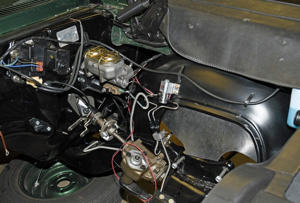
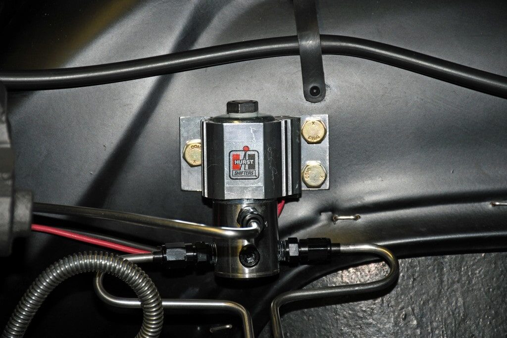
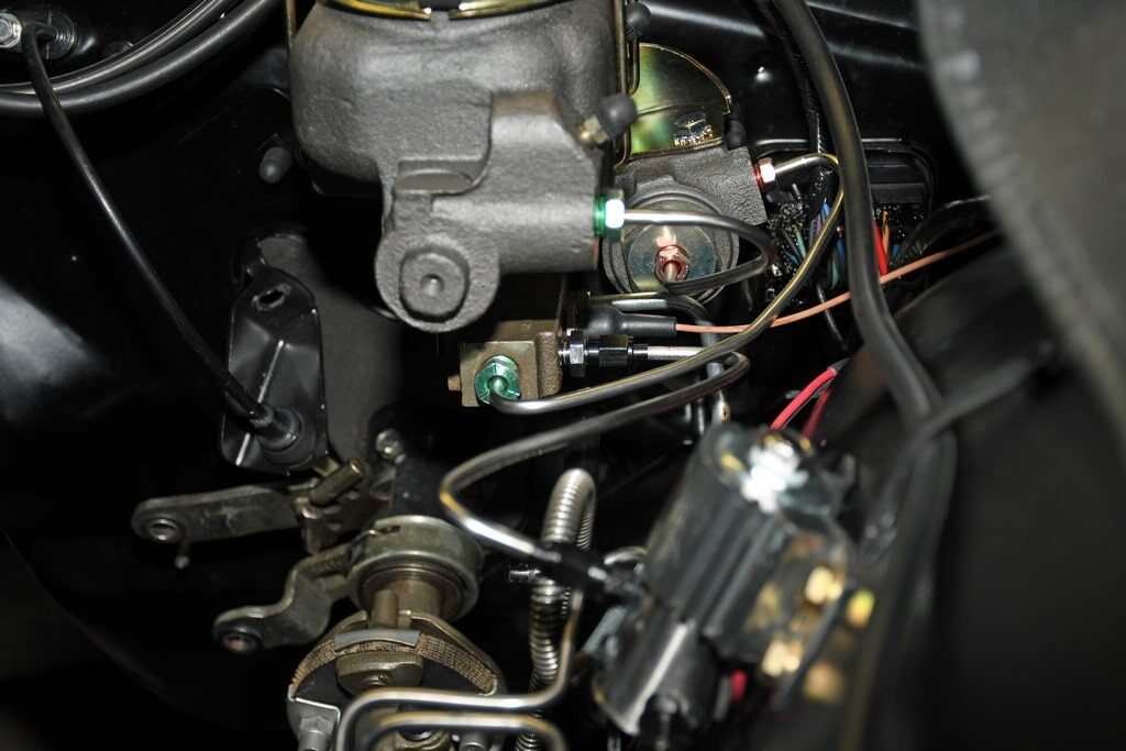
The first step is to mount the "valve" in the engine compartment. It’s a good idea to pick a mount location relatively close to the master cylinder. This makes for easier plumbing. For most cars, the most obvious spot is on the driver side inner fender well. With a Hurst Roll Control, you’ll need three fasteners to mount it (Hurst includes three big sheet metal screws – I prefer to use a trio of short AN bolts and lock nuts).
As far as plumbing is concerned, there isn't one accepted method of hooking up the system. Factor in something like an aftermarket brake system with a prop valve and you can see the plumbing will differ from something like an early car with drum brakes on all four corners. With later cars that make use of a brake distribution valve, you must plumb it after the distribution valve, not before it. FYI, Hurst provides a series of diagrams showing the plumbing requirements for most common master cylinder arrangements.
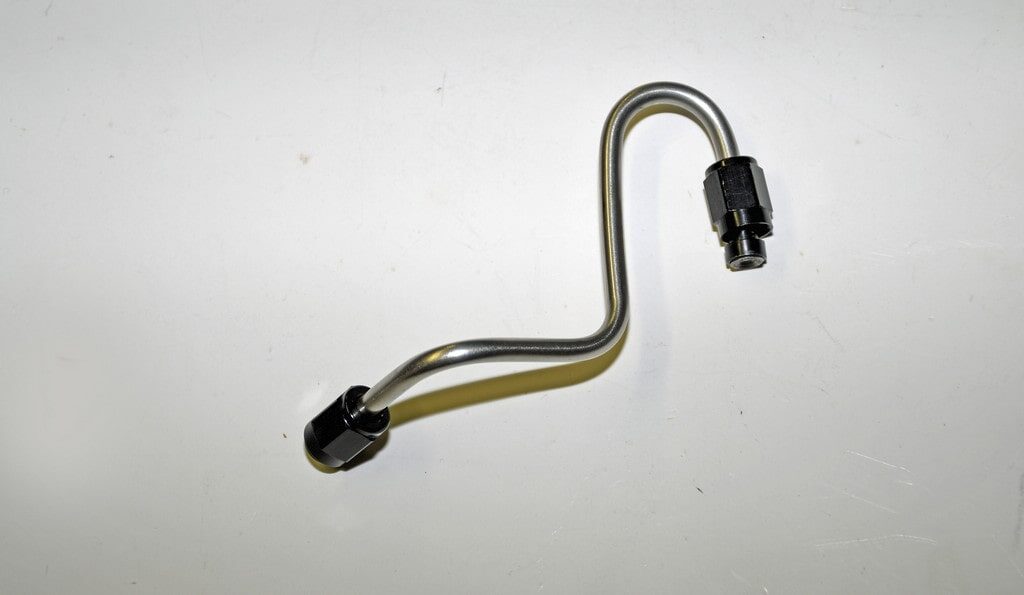
Due to the fact that several lines will require fabrication, you’ll need a flaring tool along with a tubing bender. When hand building your own line, be sure to use seamless steel or seamless stainless tubing that is designed specifically for brake use. 3/16-inch line is the preferred size.
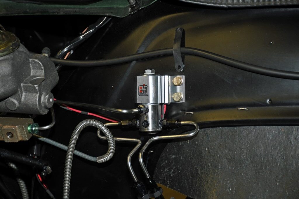
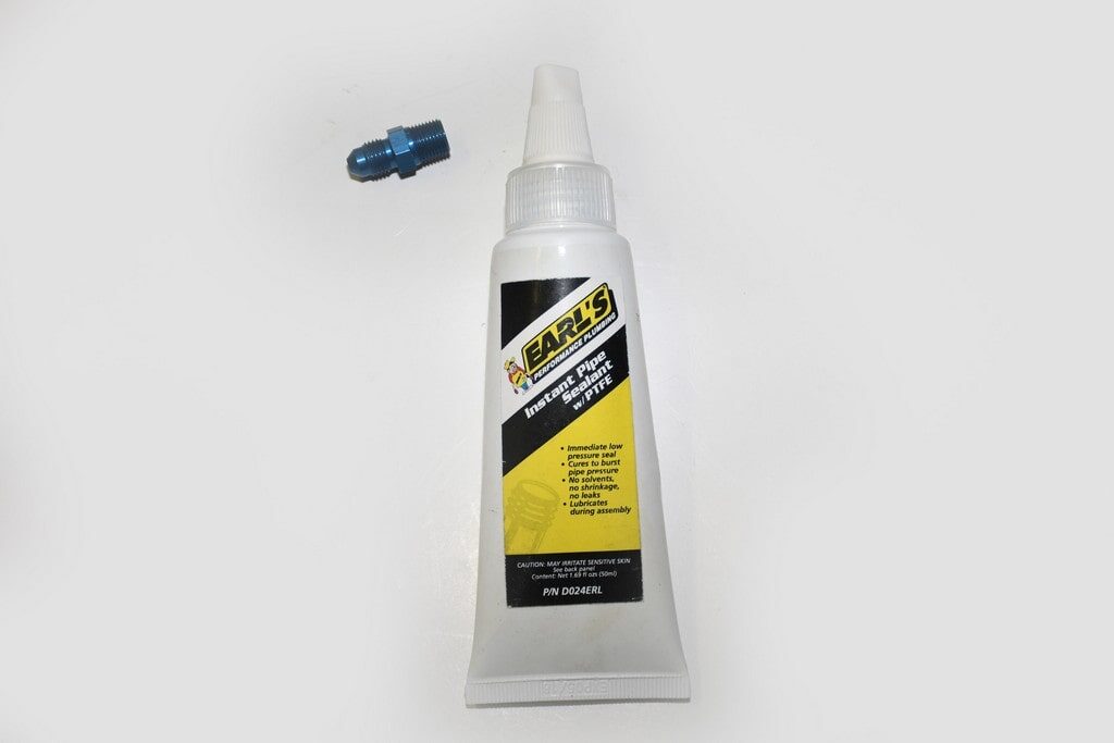
When plumbing a roll control, keep in mind most of the solenoid valves have the respective ports machined in pipe thread. If you’re using AN fittings (as shown in the accompanying photos), you’ll need AN to pipe thread adapters. When installing any pipe thread fitting (including adapter fittings), the pipe thread side requires Teflon tape or Teflon based thread sealant. You must also ensure that none of the sealant gets inside and contaminates the lines or the roll control valve.
In the photos that follow you’ll see one way of plumbing a roll control. Caution here! it may not work for your specific application. The traditional way of plumbing is to use one “out” line from the solenoid to a “T” and then back to each front brake line (this is the method Hurst recommends). Keep this in mind when plumbing your car.
Next issue, we’ll wrap up the installation with the electrical part of the equation. It’s not difficult, but you can’t leave out any steps. Watch for it! In the meantime, check out the accompanying photos:
I was most definitely in awe of Lee Shepherd (Reher-Morrison-Shepherd). Not only was he an incredibly skilled cylinder head porter, he was also one of the best (if not the best) drivers of the vintage Pro Stock era. I spent time watching him race whenever I could. What really made me pay attention was how fluid he was when performing a burnout. I was jealous! In fact, I think a lot of others were too.
Obviously, the car was equipped a Hurst Roll Control - no brainer! Then one day when I had close look at the Reher-Morrison Camaro (you could rub shoulders with the Pros back then), I spied something a wee bit different. It was a distinctive pressure gauge. A little more investigation determined it was a brake pressure gauge. This mechanical edge allowed Lee to pump the brakes to the same pressure each and every time. It also contributed to his ability to perform the same super-smooth burnout and staging ritual consistently. This setup also allows you to pre-stage, reset the line lock and then bump the car forward and complete the stage and/or deep stage.
Back to today (but keep the above in mind). Now, performing a burnout in a car isn’t that tough with an automatic. We’ve all done it: one foot on the brake and another on the gas. Sure, it raises havoc with the back brakes, but it still cooks the tires nicely. Doing the same thing with a stick is another matter. It’s next to impossible. And that’s where a line lock or roll control enters the equation. It’s basically the piece of the puzzle that allows you to perform a burnout seamlessly.
In terms of layout, the Hurst Roll Control (which happens to the be class of the field) consists of an electric valve plumbed into the brake line(s), a micro switch to operate the system and a red "On" warning lamp. When drag racing, the Roll Control is used during burnouts and staging. To set up the operation, the brake pedal is pumped a couple of times to ensure line pressure to the front brakes and with the brake pedal depressed, the roll control switch is engaged. At this point, the foot brake pedal is released. Pressure to the front brakes is maintained, but pressure to the rear brakes is released. This means the front brakes are locked. The warning lamp will glow once the roll control is engaged. You can put the car in the appropriate gear and, if it’s a stick, hit the gas and release the clutch. Or, with an automatic, simply nail the gas pedal. Obviously, you’re now performing a burnout.
Installation isn’t difficult, but given the fact it involves the brakes, take the installation seriously! Brakes are critical components! Here's how it's done:
The first step is to mount the "valve" in the engine compartment. It’s a good idea to pick a mount location relatively close to the master cylinder. This makes for easier plumbing. For most cars, the most obvious spot is on the driver side inner fender well. With a Hurst Roll Control, you’ll need three fasteners to mount it (Hurst includes three big sheet metal screws – I prefer to use a trio of short AN bolts and lock nuts).
As far as plumbing is concerned, there isn't one accepted method of hooking up the system. Factor in something like an aftermarket brake system with a prop valve and you can see the plumbing will differ from something like an early car with drum brakes on all four corners. With later cars that make use of a brake distribution valve, you must plumb it after the distribution valve, not before it. FYI, Hurst provides a series of diagrams showing the plumbing requirements for most common master cylinder arrangements.
Due to the fact that several lines will require fabrication, you’ll need a flaring tool along with a tubing bender. When hand building your own line, be sure to use seamless steel or seamless stainless tubing that is designed specifically for brake use. 3/16-inch line is the preferred size.
When plumbing a roll control, keep in mind most of the solenoid valves have the respective ports machined in pipe thread. If you’re using AN fittings (as shown in the accompanying photos), you’ll need AN to pipe thread adapters. When installing any pipe thread fitting (including adapter fittings), the pipe thread side requires Teflon tape or Teflon based thread sealant. You must also ensure that none of the sealant gets inside and contaminates the lines or the roll control valve.
In the photos that follow you’ll see one way of plumbing a roll control. Caution here! it may not work for your specific application. The traditional way of plumbing is to use one “out” line from the solenoid to a “T” and then back to each front brake line (this is the method Hurst recommends). Keep this in mind when plumbing your car.
Next issue, we’ll wrap up the installation with the electrical part of the equation. It’s not difficult, but you can’t leave out any steps. Watch for it! In the meantime, check out the accompanying photos:
I’ve used the Hurst unit before, but the last one I tried wouldn’t release properly.
I returned it and bought a Jeg’s branded unit that just felt like better quality.
It has a brass valve body instead of aluminum, and it works great on my 1995 7-liter LS powered RX-7.
One thing to remember when installing these, you need to be aware of how your ABS system will interact with it.
My RX-7 doesn’t activate the ABS if the brake lights are not on, so I had no issues simply plumbing it into the front brake line between the master cylinder and the ABS pump.
If your ABS does activate when the line-lock is active, you’ll need to plumb a solenoid in between the ABS pump and each front brake caliper, so you’ll need two units controlled by one switch.