You can install new shocks and leaf springs. You can install four bar suspensions or ladder bars. However, because you’re dealing with a solid axle on your 67-69 Camaro, you’re never going to get it to handle very well at speed. If you want the full benefit of modern technology in it, you need an independent rear suspension so each side can react to road conditions without affecting the other wheel. Racing Junk is going to take you through the steps to install the Heidts Pro G IRS.
Installing the Heidts Pro-G IRS System in a 67 to 69 F-Body
You can install new shocks and leaf springs. You can install four bar suspensions or ladder bars. However, because you’re dealing with a solid axle on your 67-69 Camaro, you’re never going to get it to handle very well at speed. If you want the full benefit of modern technology in it, you need an independent rear suspension so each side can react to road conditions without affecting the other wheel. Racing Junk is going to take you through the steps to install the Heidts Pro G IRS.
Tools and Supplies Required for This Project
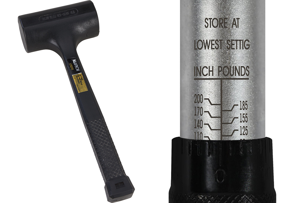
You’re going to need your complete toolbox for this project-wrenches, sockets, extensions, dead blow hammer, etc. You’ll also need a couple bottles of your favorite gear oil and brake fluid. Here’s a list of the rest of what’s needed:
• Jack, jack stands, and wheel blocks for the front wheels
• Lug wrench or impact gun (preferred)
• Line wrenches
• RTV Blue or Black
• Threadlocker Red or Green
• Level
• Mig welder (optional but recommended)
• Wire wheel
• Hack saw (optional)
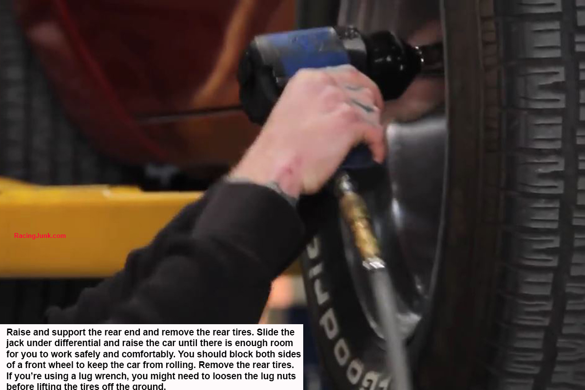
Start Off by Getting the Rear in the Air and the Wheels Off
If you don’t have access to an impact gun and appropriate sockets, this job is going to take you significantly longer than have these tools will take. Park the car on a firm and level surface to do this project. Place jack stands under the frame rails in front of the leaf springs and carefully lower the car onto the stands. The exhaust system from in front of the differential back must be removed to make room for the installation and operation of the Pro G IRS.
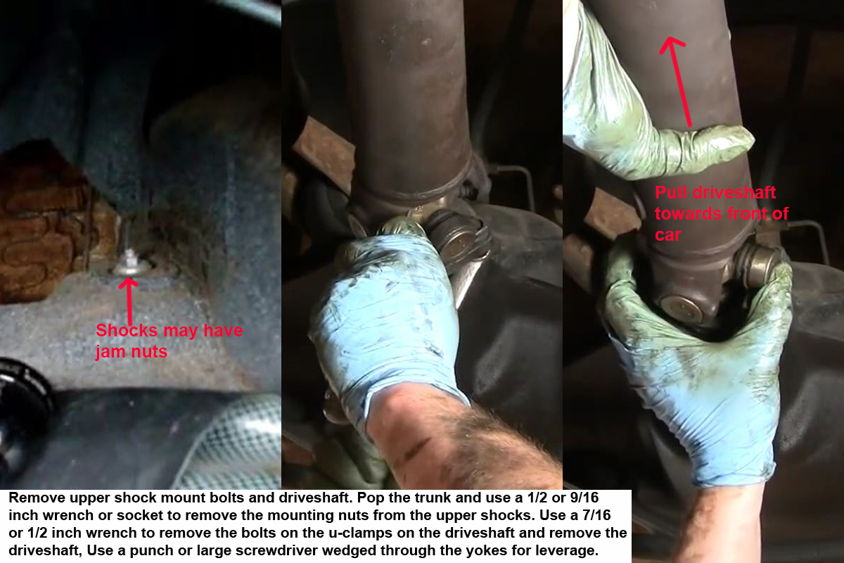
Remove the Upper Shock Absorber Mounting Bolts and Driveshaft
There are four bolts that secure the driveshaft to the pinion yoke that have to come out. Tie the driveshaft out of your way or remove it completely. If you remove it completely, remember that your automatic transmission might leak out the tailshaft. The upper shock moiunt nuts can be found either in the trunk or under the rear seat.
Disconnect the Rear Brake Lines
In order to drop the rear end housing, you need to disconnect the hydraulic system supplying the brakes. Locate the main brake line from the front and either disconnect it from the diverter block or if the block is mounted to the underside of the car’s body, disconnect the lines to the rear wheels.
Remove the Exhaust
After you’re done installing the IRS, you’ll need to install an exhaust system that doesn’t hit it while you’re driving.
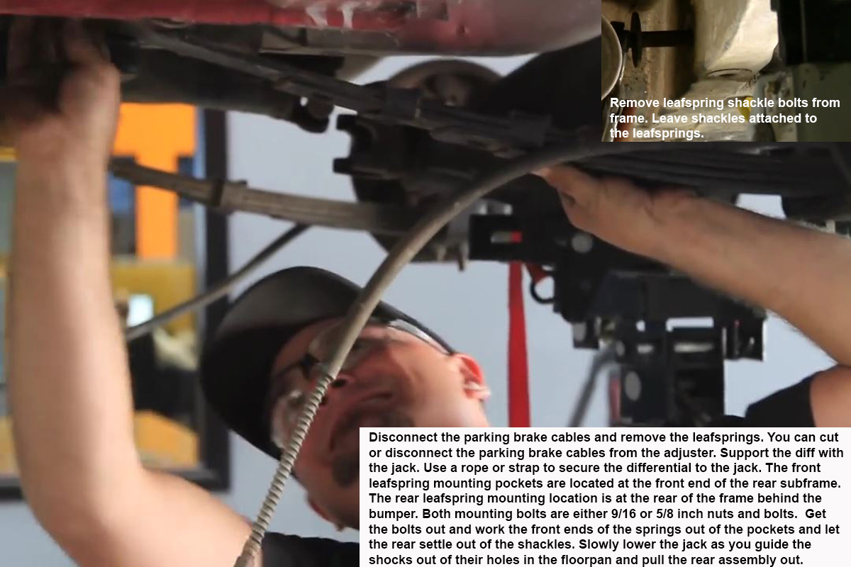
Remove the Leaf Springs and Lower the Rear End Assembly Out of the Car
You can either cut the bolts that secure the springs in the car or use a wrench and socket to remove them. However, it’s much easier to cut them.
Now that you’ve got everything securing it into the car loose, it’s time to carefully lower the rear end assembly (shocks, leaf springs, differential, and brakes) out of the car. Slowly and carefully let the jack collapse a few inches and then you and a friend both work the leaf springs out of their front pockets and help the shock absorbers come down. Make sure everything is clear and lower the jack the rest of the way. Pull the jack out from under the car and lift the rear end assembly off it and set it aside.
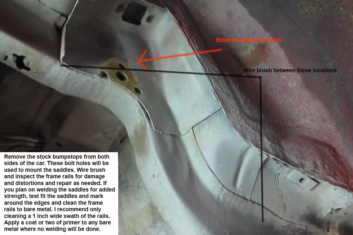
Prep the Frame for IRS Assembly Installation
This is an important step to ensure the strength and integrity of the installation.
Assemble Coilovers
Don’t lose the Jesus gasket. They aren’t easy to find and are required. Also don’t strip the screws on the adjuster or break the adjuster by tightening the screws too much.
Assemble Outer Uprights
The hub bolts need to run through the outer uprights and then thread into the hubs.
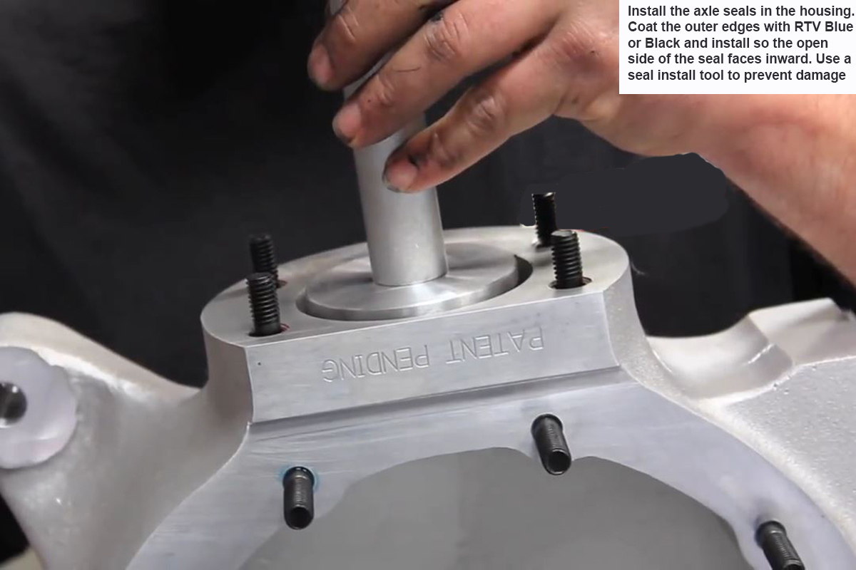
Install Axle Seals
Using a seal installation tool greatly decreases the possibility of damaging the housing and/or seals.
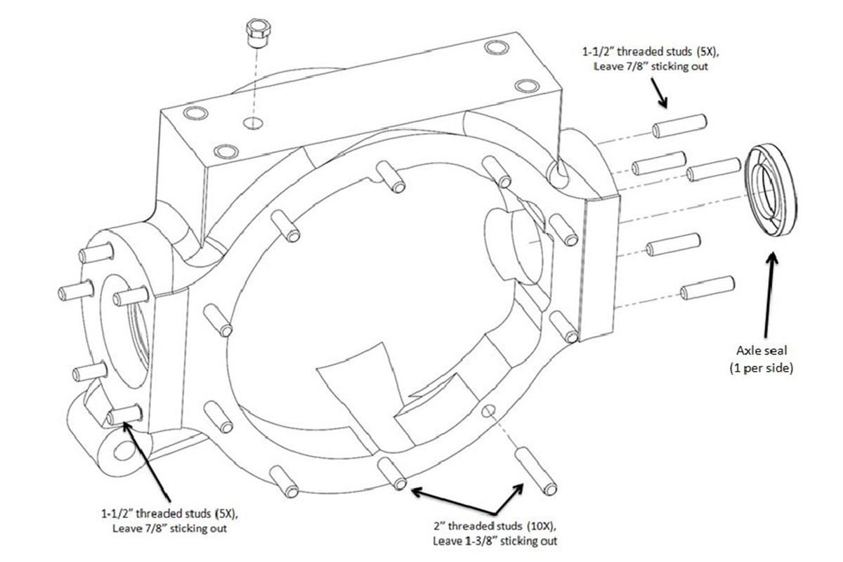
Install Studs in Housing
Measure how much the studs are left exposed two or three times before the Threadlocker is able to dry.
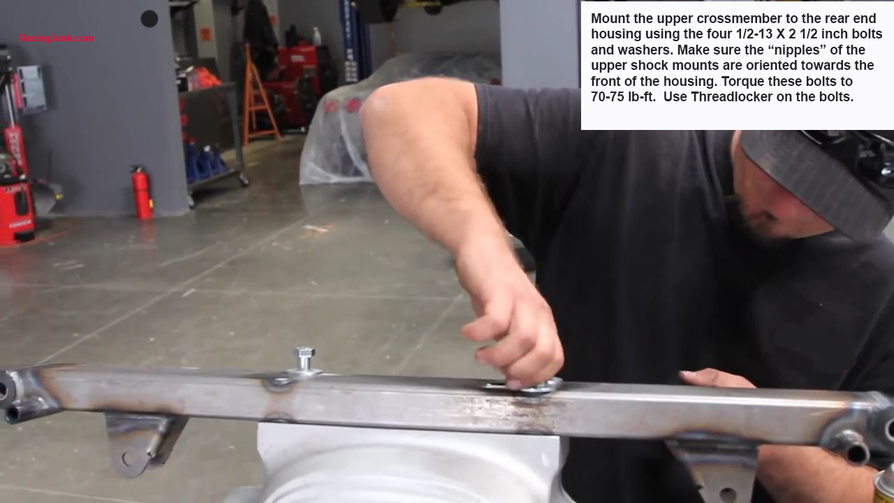
Mount Crossmember to Housing
The bolts should be installed through the mounting brackets front to rear.
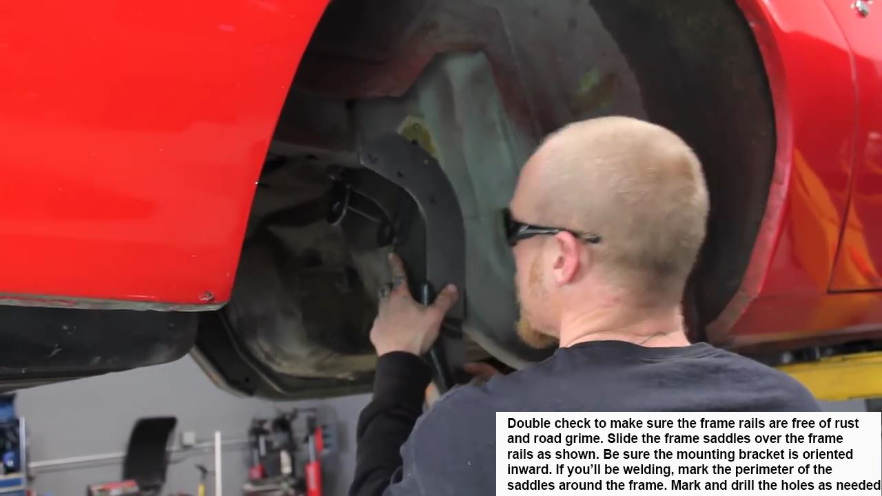
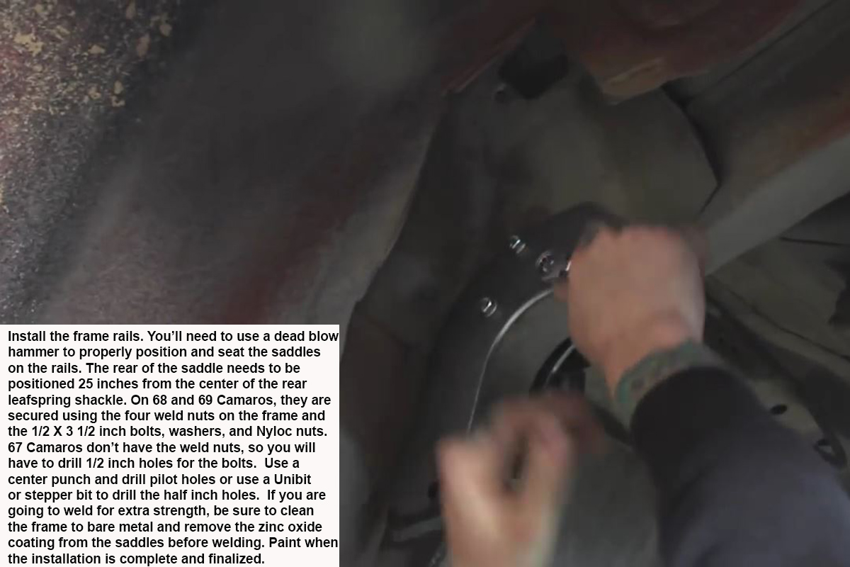
Install Saddles
The bolt holes on the front of the saddles will need to be drilled to half inch using the saddles as a template. Use the ½ X 3 ½ inch bolts, washers, and Nylocs. Use washers on both sides, between the bolt heads and the saddles and between the saddles/frame rails and Nylocs. When doing final assembly, use Threadlocker on the threads. Because this kit uses Nyloc bolts, there is no torque spec; just get the bolts tights.
Install Crossmember Assembly
Slide the ½ X 6 ½ inch bolts into the upper shock mount sleeves from the front before lifting the crossmember assembly into place. This is because the floorpan will block this once the crossmember is installed.
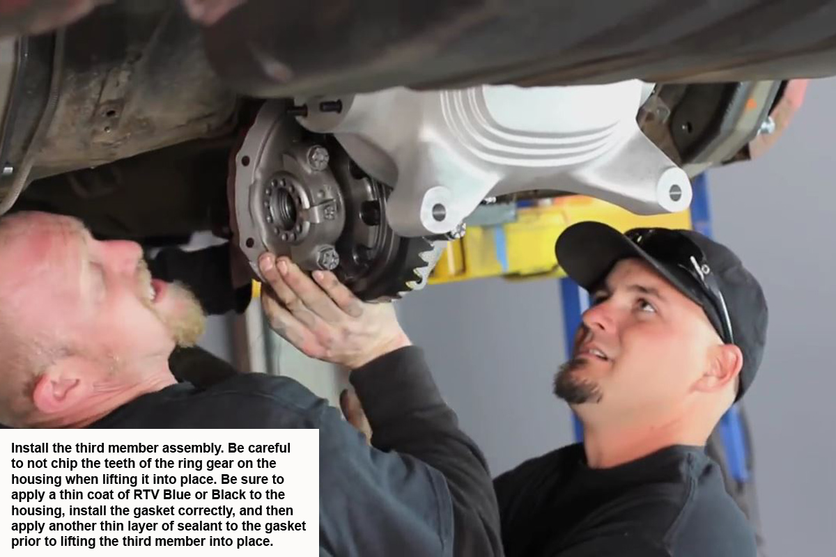
Install Third Member
Use the small Nyloc nuts and washers to bolt the third member to the housing. There are ten of each. If you’re supplying your own third member, be sure it’s a 31 spline unit as the axle stubs with the kit are 31 spline units.
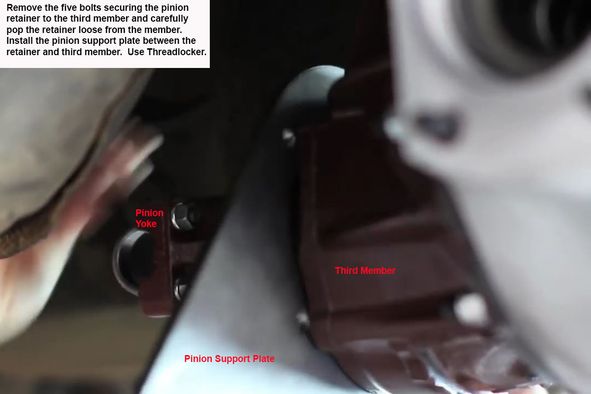
Install Pinion Support Plate
Use the supplied bolts to secure the pinion support plate to the pinion retainer. For aluminum housings, use the fine thread bolts, while the bolts with the coarse threads are for iron housings.
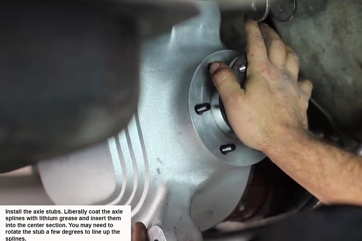
Install Axle Stubs
When installing the axle stubs, be sure to apply lithium grease to both the splines and the area on the stubs where the seal rides. Also remember that the stub with the longer shaft goes in the passenger side.
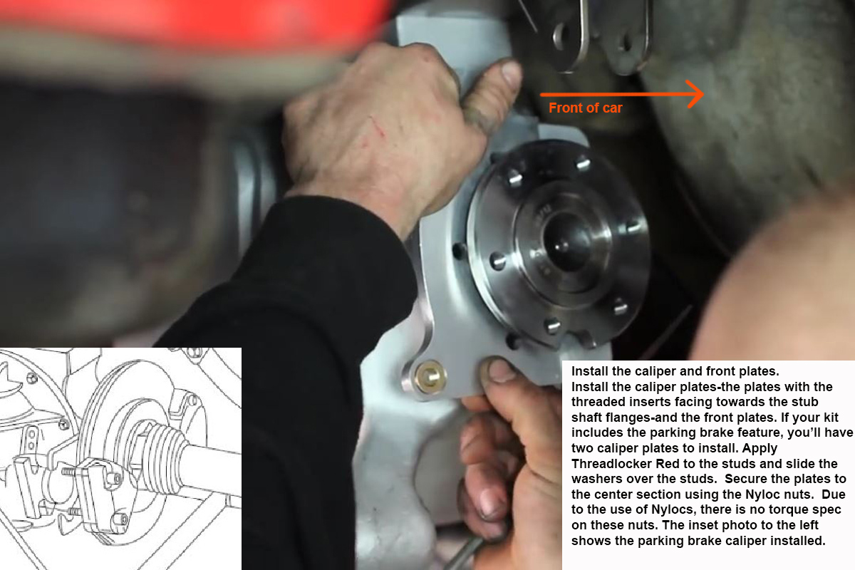
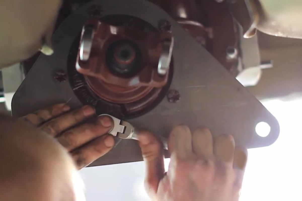
Install Caliper Plates
Rotate the stub axles to get at the Nyloc nuts with a socket and ratchet for tightening.
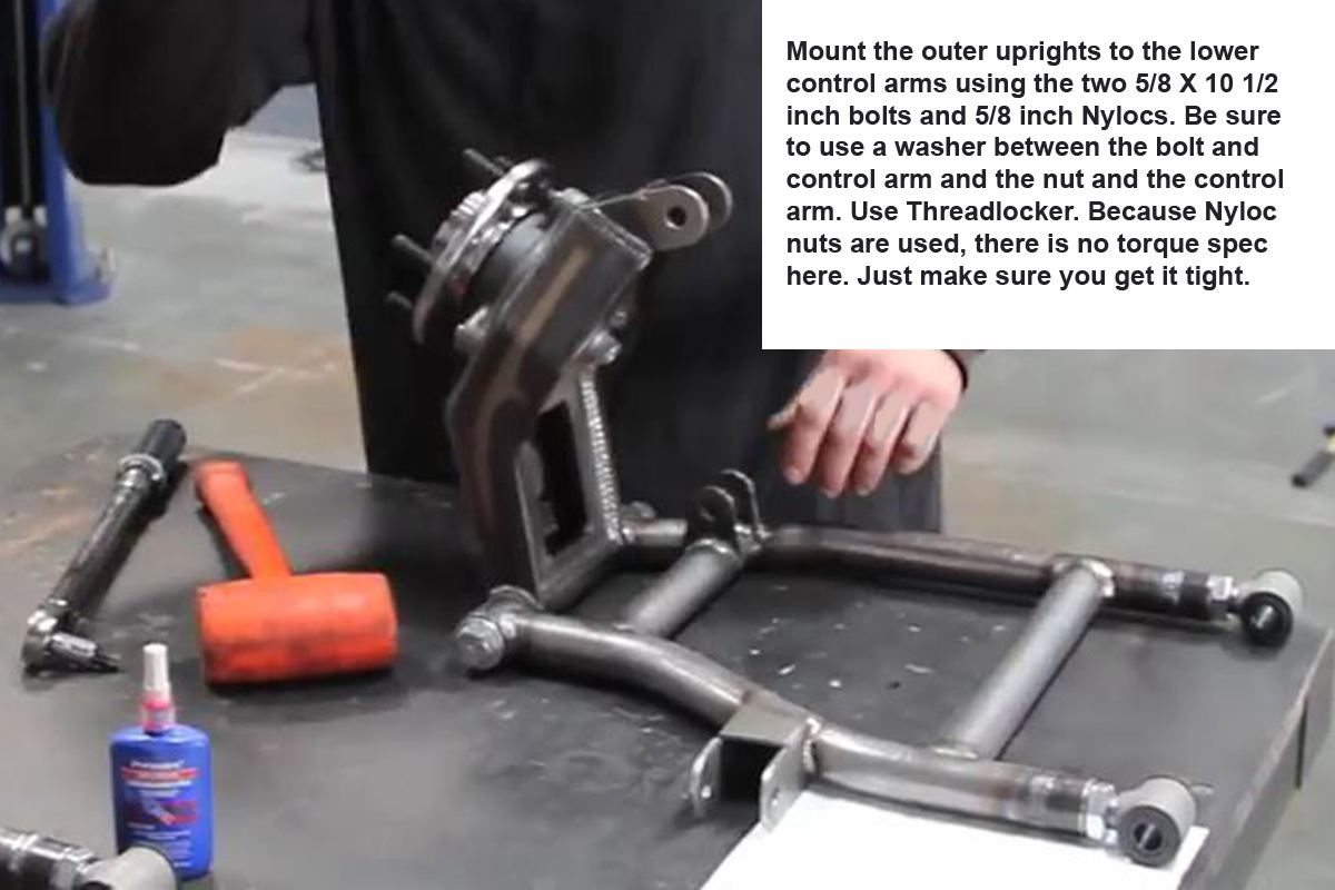
Mount Uprights to Lower Arms
Light taps with a hammer might be needed to persuade the bolts to go all the way through both sides of the lower control arms.
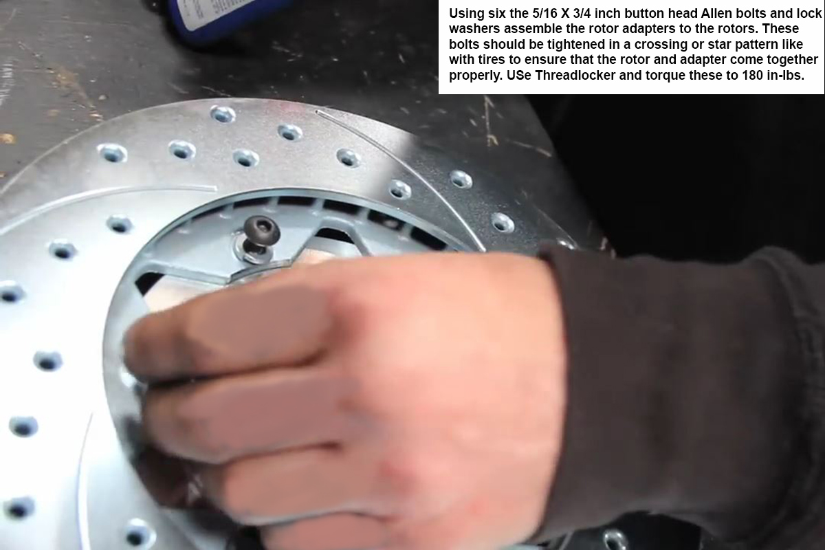
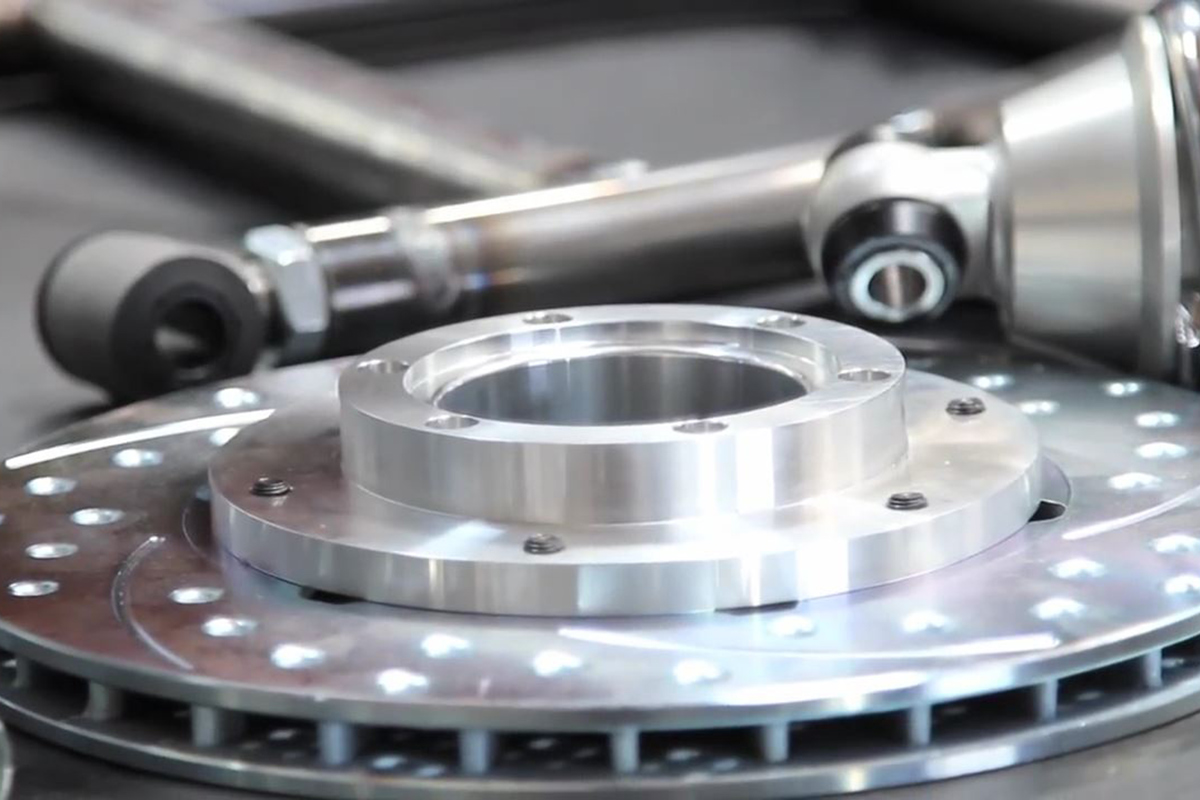
Assemble Rotors
Make sure you double check the setting and scale in use on the torque wrench before torgueing these bolts.
Attach Lower Control Arms
Don’t Threadlock or tighten the mounting bolts until after the alignment is done at the end of the installation.
Attach Outer Uprights
Run the long bolts through from front to rear.
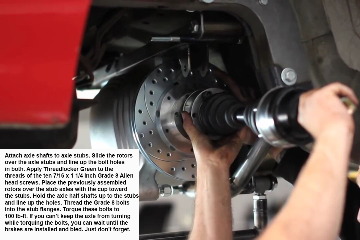
Attach Axles to Stubs
There is a tag on the inner CV joint housing with the proper torque spec for the Grade 8 Allen head bolts.
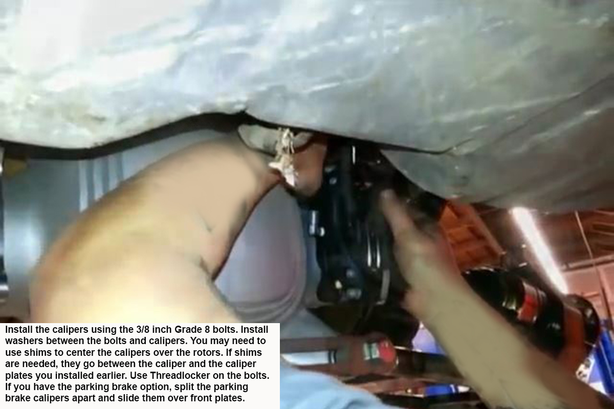
Install Calipers
Installing the new brake lines to the calipers prior to installing the calipers will make installing the lines easier. Route the new brake lines to the main line from the front and connect the three using a three-way brass block and connect. Bleed the brakes.
Install Upper Arms
Install the bolts front to rear.
Install Coilovers
Install the bottom bolts front to rear to match the upper bolts and the control arm bolts.
Install Subframe Connectors
A Unibit negates the need to drill pilot holes and use multiple bits.
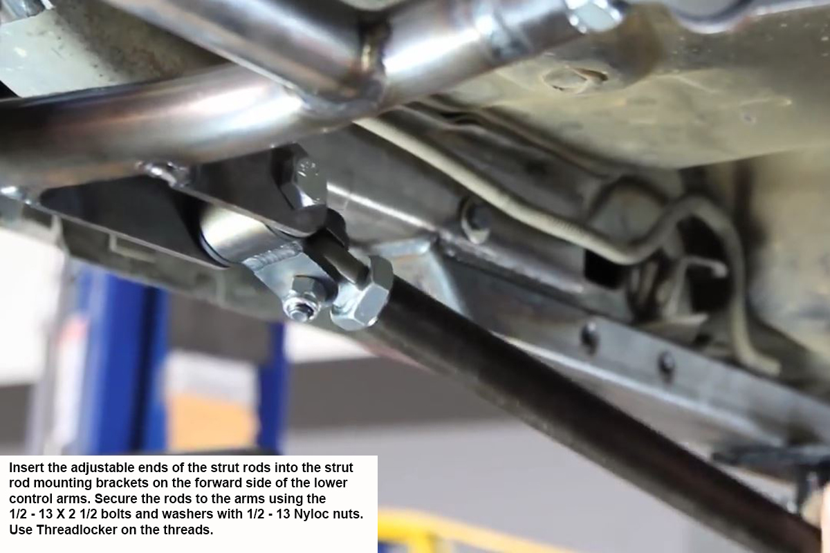
Install the Strut Rods on Lower Arms
Make sure this end is the adjustable end. The jam nut can be tightened because a caster adjustment shouldn’t be needed.
Install the Strut Rods in Subrframe Connectors
This has to be the non-adjustable end.
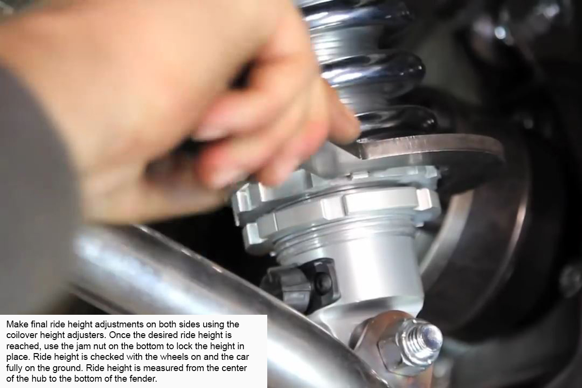
Adjusting Ride Height
Get the ride height close by measuring from the hub to the fender, but the final adjustment needs to set the lower control arms and axle shafts as close to horizontal as possible.
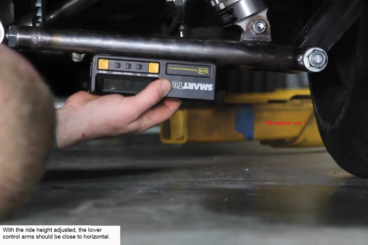
Checking Ride Height
Make sure the axles are close to horizontal as well as the lower control arms.
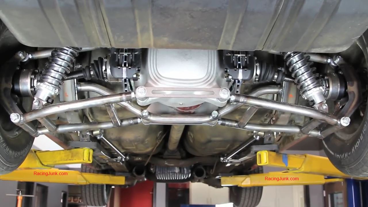
Completed
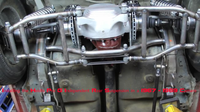
This is what the Heidts Pro G Independent Rear Suspension looks like when the installation is complete.
Align
To make the rear alignment as accurate as possible, this measurement/reading should be taken with the weight of the car on the suspension. The wheels should be installed and the car fully lowered onto them. You will have to lift the rear of the car to adjust the camber using the lower control arm adjusters.
Mike's love of cars began in the early 1970's when his father started taking him to his Chevron service station. He's done pretty much everything in the automotive aftermarket from gas station island attendant, parts counter, mechanic, and new and used sales. Mike also has experience in the amateur ranks of many of racing's sanctioning bodies.
2 Comments on Installing the Heidts Pro-G IRS System in a 67 to 69 F-Body
Looks like a Jag rear axle with inboard disk brakes!


![[Gallery] Street Rodders for Life Memorial Day Car Show](https://www.racingjunk.com/news/wp-content/uploads/2026/06/Memorial-day-show_0198-376x206.jpg)
![[Gallery] Townsman Car Show](https://www.racingjunk.com/news/wp-content/uploads/2026/05/916_2843-e1780072552171-376x206.jpg)

Looks like a Jag rear axle with inboard disk brakes!
It does look a little like a Jag rear. However, it’s 100% made by Heidts in the USA.