


Your car’s alignment is what causes it to remain stable while you’re driving down the road. A properly set alignment will compensate for what is known as road crown – roads are sloped slightly to cause water to run off more quickly – while still being able to maintain a straight track. An alignment that is improperly set can cause your car to want to pull to one side or another or require more effort to make steering inputs. An improperly set alignment will cause your tires to wear unevenly.
In this article, we’re going to discuss the three alignment angles that affect your alignment and how they interact with each other. I will next go into the different types of alignments that are performed today. Finally, I will detail some tricks I’ve learned over the years that you can use to correct minor alignment issues. Unless you have a magnetic camber gauge, you won’t be able to check caster, so we’ll only deal with the camber and toe here.
The Three Alignment Angles that Are Dealt with During an Alignment
There are three alignment angles that we can measure and adjust on most cars, camber, caster, and toe. Camber describes the angle of the tire in relation to the perpendicular – straight up and down. Caster describes the angle between a line drawn between the ball joints (on older cars, on newer cars it describes the angle between the MacPherson strut) and the king pin or steering knuckle. Toe describes the angle between an imaginary straight line drawn down the centerline of the vehicle between the front and rear bumpers and an imaginary line drawn through the center of the tires.
Caster is often referred to as the steering assist alignment angle. When caster is set properly, it helps you make the turns you’re commanding more easily and when you’ve completed the turn, caster also helps the steering wheel return to center. Caster has to be set properly because it causes the tire to lean in or out when you turn the wheel. Too much or too little caster and you end up with too much camber through hard turns, which can cause a loss of traction. Also, because caster causes the tire to lean in turns, it also has an effect on tow.

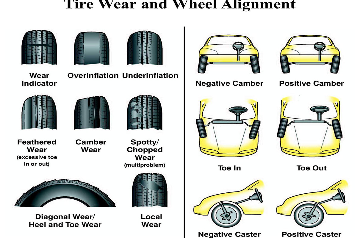
If only camber is out of spec, you’ll see excessive tire wear pretty evenly around the inner or outer section of tread. Excessive negative camber (inward lean of the tire) will present as excessive wear along the inner portion of thread while positive camber (an outward lean on the wheel) presents as outer edgewear. For performance street vehicles, we’re typically looking for a camber reading of no more than one degree negative. For road course racers, we might go as high as 1.5 degrees. Oval track cars are different, though, because they only have to deal with forces in one lateral direction. Passenger side camber will be almost two degrees positive while the driver side will be closer to two to three degrees negative.
Improperly set toe can wear either edge, depending on if it’s toe in – the front of the wheel pointing to the inside of the car (pigeon-toed), or toe out – front of the tire pointing outward. The wear pattern will not be regular around the circumference of the tire. It will be “feathered” or irregular. Some of the wear may extend more than a third of the way towards the centerline of the tread while other worn portions may be quite small.
The Different Types of Alignments We Can Perform
back in the day, there was only one type of alignment that could be performed and this was the straight front wheel alignment. We used strings, tape measures, and magnetic bubble gauges to take our measurements. Today, we have alignment machines that use lasers to obtain much more accurate measurements.

The type of alignment most of us with strip burner hot rods can get is the thrust alignment. This type of alignment takes all four wheels into consideration when measuring toe. Instead of measuring where the front wheels point in relation to the imaginary line drawn down the front to rear centerline of the car, we base our readings of where the rear wheels are pointed. This is because while rare, things can happen that throw the rear wheels out of whack enough to make a difference, but not enough to be seen with the eye or felt in the hands or butt while you’re driving, and we need to compensate for that drift when we adjust toe.
The final type of alignment we can do these days is the four wheel alignment. When we do this kind, we measure camber and toe of the rear wheels based upon that imaginary front to rear centerline of the car. Most newer cars let us adjust camber and toe on all four wheels. Adjusting rear camber and toe can be time consuming and frustrating, but it can be done, usually using shims between the axle plate and the backing plate.
Checking Camber Visually – No Tools
Camber problems will normally cause your car to pull to one side or the other due to the tire(s) leaning, similar to how you can turn your bicycle simply by leaning one way or the other without turning the handlebars. You can visually check camber, “eyeball it,” just by looking at the tire with the car parked on a flat and level surface and the wheels pointing straight ahead. You won’t get good accuracy and without a trained eye, it’s got to be a degree or more out of whack, but it can be done with zero tools except the Mark IA Eyeball you were born with.
Checking Camber with a String/Paint and Protractor
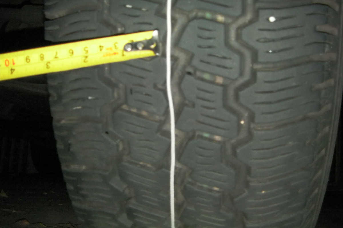
 For this test, you’ll need to nicely ask your child if you can borrow their geometry protractor. Park on a flat and level surface and raise the front wheels. Tightly wrap a piece of string around teh tire and use a tape measure or ruler to make sure it is equidistant from one edge of the tire around the full circumference of the tire. I know people that use paint to do this, but I prefer string or even a piece of coaxial cable because it’s easier to ensure that the line is straight.
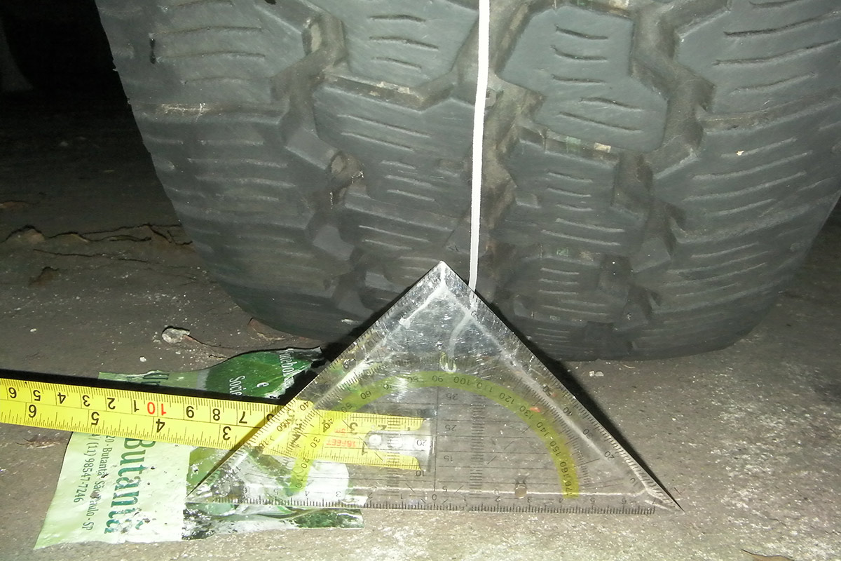
Lower the car completely and remove the jack. Remember, this has to be done on a surface that is both as level and as flat as possible, your inclined driveway won’t do. Now, place the protractor on the ground in front of the tire so it touches the string and the zero degrees indicator at the bottom of it is lined up with the string. Look at the top of the protractor to see where the string touches it where the graduations are marked. This is your “eyeballed” camber reading. The pictures above give a good representation of this. To the left of the zero is negative while to the right is positive.
Checking Toe with a Tape Measure
If you can use a tape measure, do math, and have a helper, this method of checking toe can be just as accurate as the laser machines we use in the shop. Center the steering wheel without worrying about the tires yet and lock the steering wheel. Measure and mark on the inner sidewall about three or four inches up on the front and back of both front wheels. These are the points you will measure from and they need to be within no more than an eighth of an inch from each other on both wheels to be accurate.
Feed your helper the end of your tape measure at the front of the tire. Place the foot of the tape against the mark on one tire and read the measurement off the tape measure. For our purposes, we’re going to say that the fronts of the tire are 76 5/16 inches apart. Now move to the back of the tire (closer to the passenger compartment) and measure again. let’s say this measurement is 76 8/16 inches apart.
Right off the bat, we know that the tires are pigeon-toed, or toe-in, 8/16 is larger than 5/16. Subtracting the two, we get a measurement of 3/16 of toe-in. For just driving to the alignment shop, this is fine, although the spec for something like a 69 Camaro is 1/16 inch of total toe-in.
We can go one step further and get the toe splits as well. For this, we need to find the exact centerline of the vehicle front to rear. Instead of measuring tire to tire, we measure tire to centerline to find our individual toe measurement. Once we have our measurement, we divide our desired toe measurement (the specification) by two to determine what the individual toe for each side should be.
How Camber Is Adjusted on Most Older Vehicles
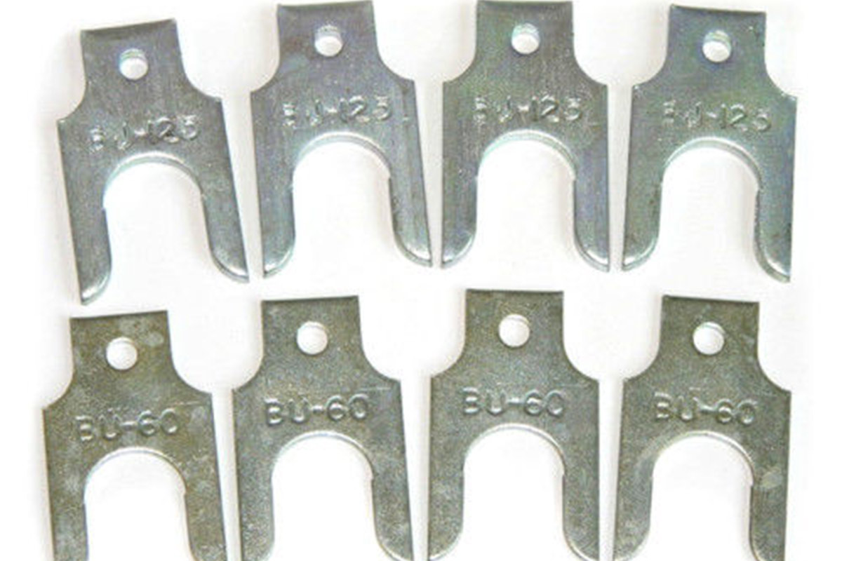
On most older vehicles, camber and caster is adjusted by the addition or removal of shims that go between the upper control arm’s pivot arm and the frame. Whether you need to add or remove shims will depend on whether the arm is mounted to the inside or the outside of the frame rail – most cars you see will have the arm mounted to the inside of the rail – and whether you need to go negative or positive with the camber. Just be sure to add or remove from both shim packs.

If the arm is mounted to the inside of the frame and you need to go negative, you need to pull the arm away from the frame, or add shims. Conversely, if you need to go positive, you pull shims. If the arm is mounted on the outside of the frame and you need to go positive, you need to push the arm away, or add, while if you need to negative, you need to pull shims. Whether you’re adding or pulling shims, make sure they are of the same thickness from front and rear. Otherwise you will also be adjusting caster.

However, if you’re looking at an older Mopar product, you have to loosen and physical move the pivot arm inboard or outboard. There is a special tool available that makes this quite a bit easier than tapping on the arm with a hammer. The arm is mounted near the center of the frame rail on these cars, such as my 74 and 65 (YES, I said 65!) Dodge Chargers.
To go negative, we slide the arm toward the engine. To go positive, we slide the arm toward the tire. This kind of vehicle is tricky to adjust because there are no shims to add or remove. The hard part is to move both the front and rear of the pivot arm the same distance. Again, if the front or rear is moved more than the other, you’ll also be changing the caster measurement and we can’t measure for this, so we don’t know if doing so is a good thing or a bad thing. Play it safe and use a tape measure to get your adjustments as close to exactly the same as you can.
Adjusting Toe
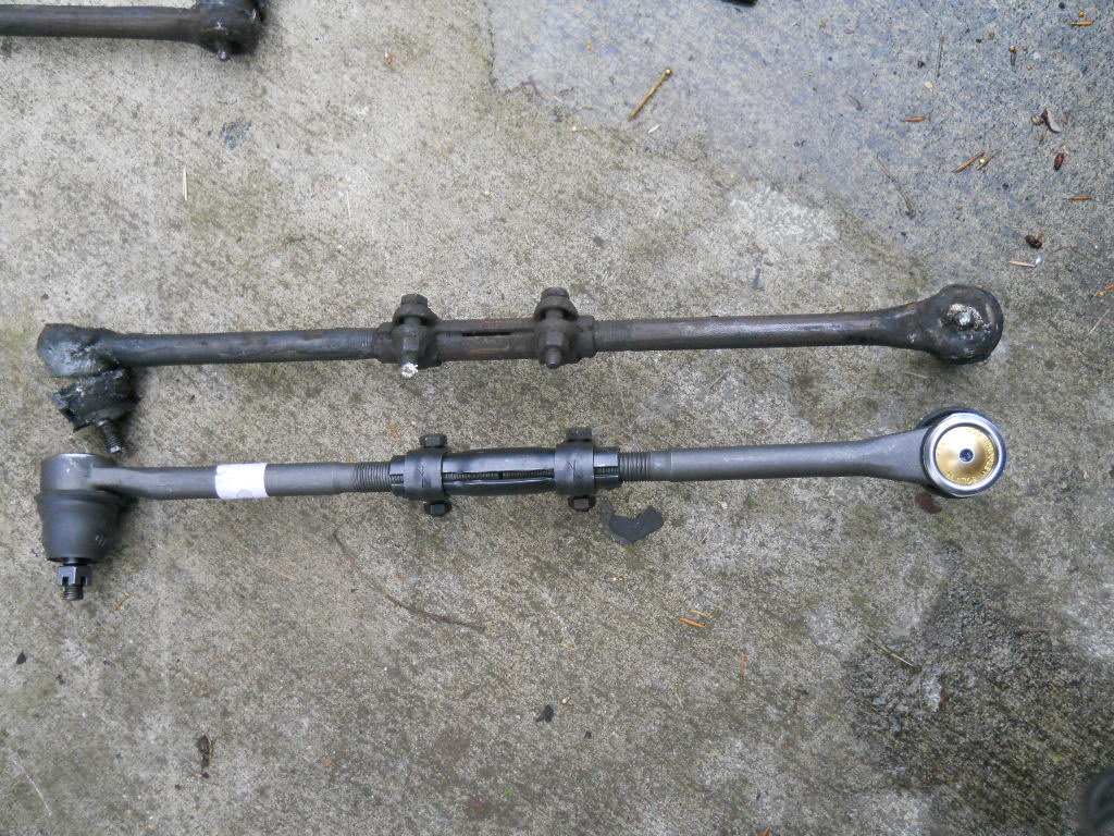
Adjusting toe is easy. On older cars, simply loosen the two nuts on the sleeve that connect the inner and outer tie rods and twist the sleeve. The tie rod ends are reverse threaded so that when you turn the sleeve on direction, it pushes them apart and the other direction pulls them together. On newer cars, those with rack and pinion steering, the locknut against the outer tie rod end is loosened and the inner rod arm is turned, effectively lengthening or shortening the distance between the rack and the tie rod.

Leave a Reply