


We’re almost finished with the JS Racing Products Parts Truck build dear readers. All that’s left now is to install the oiling system for the turbos, the intake air charge piping, and the exhaust piping. In this episode we will be using the terms “hot side” and “cold side” to refer to the exhaust and intake sides of the turbos, respectively. Craig’s got a series of videos showing the steps he took throughout this build. However, I’ve taken some of the information in those videos out of sequence because, in my opinion, it makes the process flow better. Just be aware that you should read through all four of these articles prior to starting out so you know what the whole process entails.
Installing the Turbo Lubrication System

In order to keep the bearings in the turbos from melting, you’ve got to install a lubrication system for them. On this particular generation of LS engine, there are two places you can tap for this. The first, and arguably the easiest, is the OEM oil pressure sending unit on the top of the block behind the intake manifold. The other is the block off port on the driver side of the engine. Craig chose the easier route. Just realize that if you retain the OEM oil pressure gauge, your pressure readings will be a little lower than what the pump is actually producing.

Craig went to Jeg’s to pick up the parts for the lubrication system adapters. These parts are:
- Two-inch long 1/8-inch pipe thread extension
- Four-way 1/8-inch pipe thread fitting
- Brass fitting with the correct threads to accept the oil pressure sending unit
- Brass fitting with the correct threads to thread into the four-way block
- Teflon tape
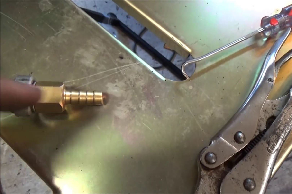
Step one of this part of the project was to cut the two fittings for the oil pressure sending unit. The female fitting that the sending unit threads into had a ¼-inch barbed fitting that needed to be removed, while the male fitting to the thread into the four-way block had to have the female portion chopped off. These were carefully brazed together.

Craig applied a generous helping of Teflon tape to all the male threads to ensure a good seal. The male pipe extension was threaded into one end of the four-way block, while the custom-crafted OEM sending unit adapter went into the opposite end. The OEM sending unit was removed from the block, Teflon tape was applied, and the sending unit was then threaded into the adapter assembly. This partially completed assembly was then threaded into the sending unit opening on the block and tightened down.

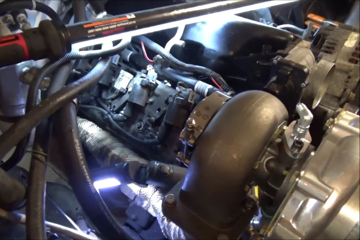
Teflon tape was then applied to the threaded ends of the Parker push-lok fittings which were then threaded and tightened into the block openings. Be sure the block fitting is tightened so that the oil line openings directly point to each side of the engine. It’s recommendable to do this part of the build with the intake manifold off if you can. You can do it with the manifold on; it’s just a bit more difficult to reach.

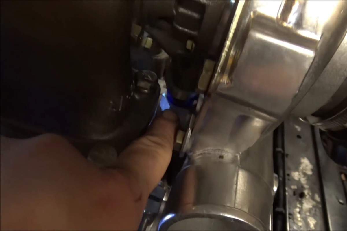
The turbo oiling fittings (both supply and drain) should be installed on the turbos prior to installation otherwise you’re going to have a helluva time getting them installed. One thing to keep in mind during the turbo installation: If you can, clock the turbos so that the oil drain fittings aren’t interfered with by the turbo bolts.

Otherwise you may have to remove one of the turbo shell bolts to fit the drain fitting. On Craig’s turbos this isn’t as much of an issue as with turbos from other suppliers, as his aren’t drilled clear through, while others are. This is going to affect how and where you can mount your wastegates and their outlet pipes, as well as the turbo air charge outlet piping.
Craig used a braided cover on his oil supply lines. This adds a little extra strength as well as looking better under the hood. When Craig cut the oil lines, he left some slack in them so as to relieve the strain at either end.
Craig installed the oil drain bungs into the oil pan when he had the pan off to install the new oil pick-up that went with the new oil pump. He used a stepper bit-some people call them Christmas Tree bits- and went in at a slight downward angle so the drain bungs we angled downward after being welded in. Craig told me: “You’ve got to be sure you angle the drain bungs downward so as to ensure that the oil is able to drain properly.” He recommends welding the bungs in from the inside. He uses a slip-in bung with a 6-AN fitting that couples to the 6-AN to 3/8-inch Parker Push-Lok fittings. Just be sure you’ve got your routing and length correct before you push the hose onto the fittings. The only way to remove the hose from the Parker fittings is to cut the hose off.
The Cold Side Part 1: Piping from the Turbos to the Intercooler

Craig used a big dual-core aluminum heat exchanger as the air-to-air intercooler for this build. You can use an air-to-water intercooler, but they are significantly more labor intensive for the amount of gain derived. He routed the piping to the intercooler right next to the radiator, running the passenger side with the condenser lines and the driver side between the radiator and the battery.
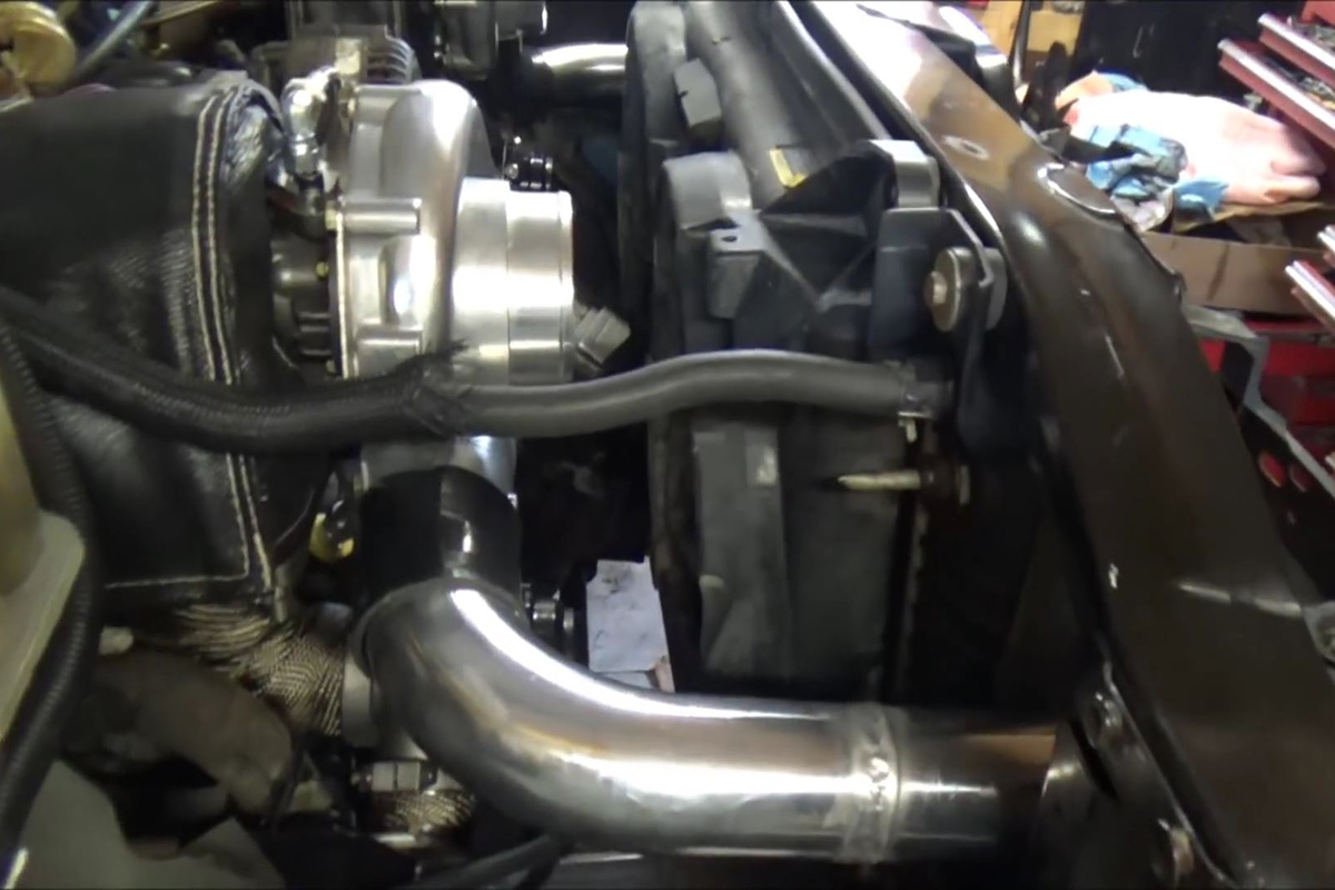
The piping is three-inch stainless-polished so it looks better. Craig also TIG-welded some of the joints as this makes the joints look nicer. You can use simple heat-resistant silicon coupler. In fact, he recommends using silicon couplers on the turbo outlet and the intercooler inlet. The silicon couplers have a little flex which helps when your stomp on the pedal, causing the engine to torque. If you weld everything solid, you run a good chance of cracking/breaking the pipes. Silicon couplers are also used to make taking things apart easier if maintenance is required.
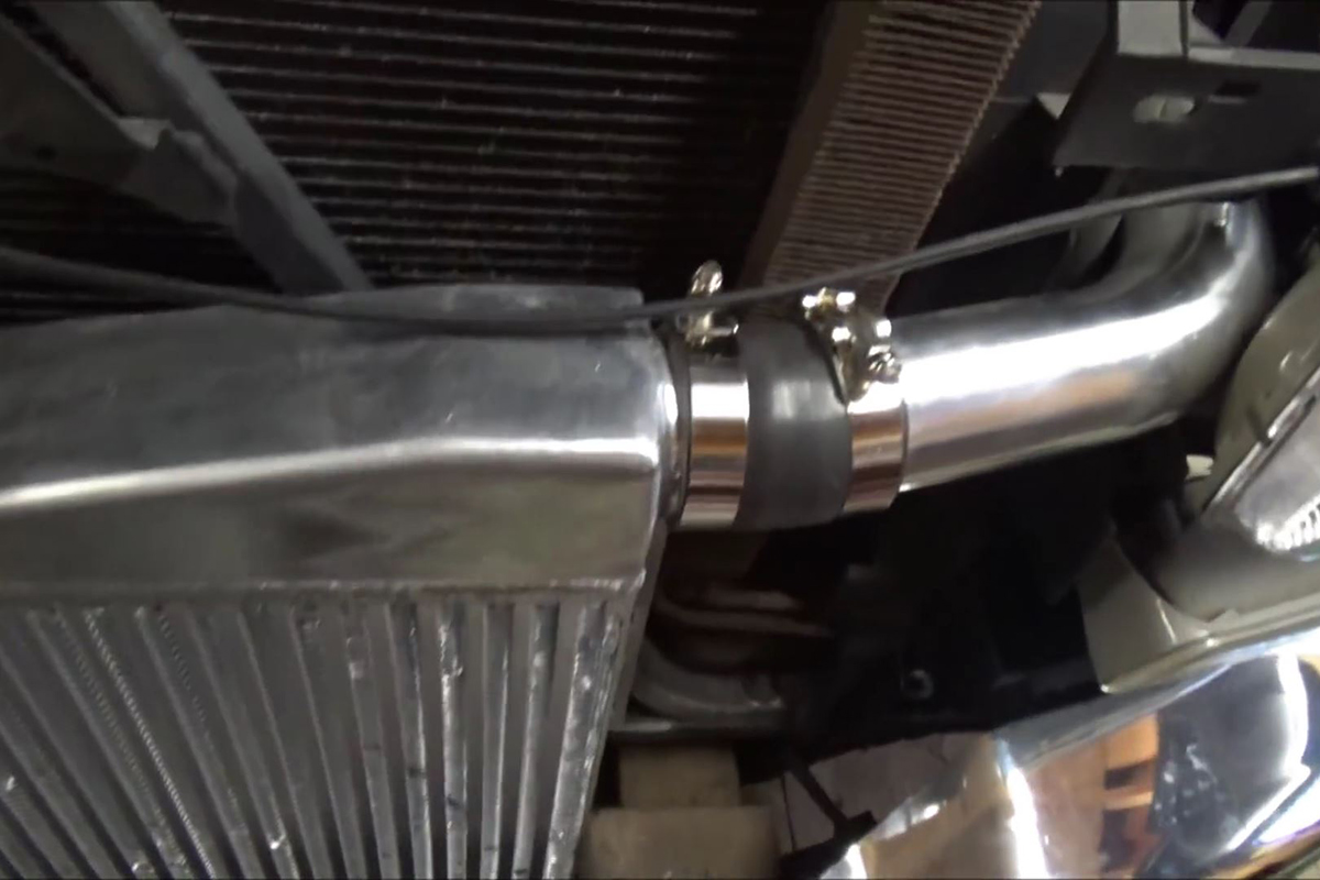
The intercooler is mounted in front of the other coolers-radiator, condenser, and trans cooler for maximum air charge cooling efficiency. Remember, colder air is denser air is air that has more oxygen that can be burned during the combustion cycle.
Craig drilled the hood latch supports to mount the intercooler. The problem I have with that is he only used two mounting holes while I prefer two on each side for extra sturdiness. Unless the vehicle you’re building will only be driven on well-cared for tracks, you should look into adding some extra bracing for the intercooler.
Cold Side Part 2: The Air Charge Piping

The air charge is the body of air that has been compressed and will be moved through the intake manifold and into the combustion chambers to be mixed and burned. Once the intercooler is mounted in front of the condenser and properly secured, and then the piping to the intercooler is finished, it’s time to pipe to the intake manifold. For Craig’s build, this is a relatively simple set of two 90 degree angled pieces and two straight pieces.
The first 90 degree piece of the air charge pipe comes out of the intake/throttle body and turns down. Craig then tig-welded a nine-inch straight piece to the end of the 90 out of the throttle body. The second 90 degree angled piece comes directly out of the intercooler, under the radiator and turns up between the fans and the block. Craig used another silicon coupler and clamps to join this to the two-piece section coming from the throttle body.
Cold Side Part 3: The Blow-Off Valve

I mentioned in a previous article that every engine with forced induction has to have a way to vent excess induction pressure to outside air. For both supercharged and turbocharged engines, this is accomplished by a blow-off valve (BOV). Turbochargers also have wastegates to vent excess exhaust pressure from the driven side of the turbo. If these components aren’t present, serious engine damage will result.
Craig mounted his BOV right in front of the intake/throttle body, on the upper 90. He did this simply for aesthetics, because it looks cool up there and because putting it there, after the intercooler means he only needs one, instead of one for each turbo . You can mount yours wherever you want on the charge side.
Craig again TIG-welded the BOV mount to the pipe because a TIG-weld is usually a cleaner weld. You can arc or MIG yours. Once he had the mount welded up nicely, he used a center punch to mark on the pipe to mark the exact center of the opening and used a hole saw to cut the required opening in the pipe. After he mounted up the BOV, he ran a vacuum line from it to the vacuum port he created on the back of his custom smoothed intake manifold. This vacuum port now supplies both wastegates, the BOV, and the ZR1 MAP sensor he installed.
The Hot Side: Routing the otHot Side
Down Pipes

Craig’s turbos have three-inch outlets, so that’s the size pipe he used for the down pipes-the exhaust hot side out of the turbos. He used parts from the three-inch Universal Rod Builder Exhaust Kit he bought from Summit Racing. Craig says: “Even if you’re doing the same build with the same parts on a 2004 GMC or Silverado truck like this, you should only use my design in these videos as a starting point because each build is unique.”

Craig also told me: “Never do a primary weld while fitting your exhaust pipes. Do a light tack on each join until you have everything where you want it and routed the way you want it. Only them should you do a primary weld on the pipe joins.” Craig’s first step on the hot sides was to take two 45-degree pipes and tack V-bands to them to mount them up to the turbo. The passenger side down pipe consists of the first 45, a short straight pipe, then another 45 with a short pipe attached. This short pipe ended about five inches past the passenger cab.

The driver side down pipe also started out with a downward-angled 45 with a short straight piece, flowing into a 45 to bring the pipe run back to the horizontal. Craig decided that he wanted to do a single exhaust, keeping with the stock look of the truck, so after the 45 to horizontal, he tacked in a 90, veering the pipe over to the passenger side. This flowed into another 90 to route the piping towards the rear and ended with another short piece to meet up with the passenger side pipe.
Once he was satisfied with the placement/routing, he welded everything up. He also welded these two pipes together. Lastly, he welded up an exhaust hanger to keep the pipes from moving around and possibly cracking the pipes or the welds under load. For extra support, Craig also used a large wormdrive clamp to tie the hot pipes to the exhaust manifolds. This also helps to prevent vibration-induced cracking .
Merging Two Three-Inch Pipes into a Single Five-Inch Pipe
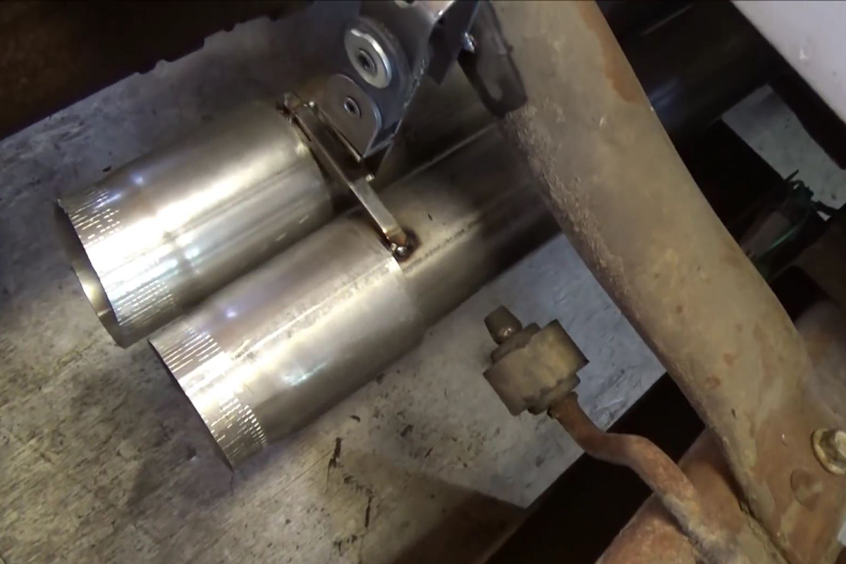
Because of the turbos, Craig couldn’t merge the two three-inch pipes into a single three-inch pipe to the rear of the truck. So, he went with a five-inch diesel-style exhaust pipe. Again, he picked this up from Summit Racing. He stuck the end of a full-size length of the five-inch pipe into his vise and squeezed it down to create an oval-shaped opening in the pipe with a height of three inches.

He then created two three-inch slide-in adapters. On side of these he swaged the pipes out just enough to slide over the three-inch exhaust pipes from the turbos. On the other side he used AC duct crimpers to shrink them down enough so they’d slide into a three-inch pipe. He then welded them together so they’d stay together. He then crammed these into the five-inch pipe that he squeezed into a three-inch tall oval.

This left gaps between the two pipe sizes, though. He could have just used his gas welder and rod to fill these gaps, but that wouldn’t have looked good. So, he used his nibblers and cut about two inches into the gaps between the two three-inch to –five-inch adapters he created, punched the edges of the cut down and placed a small piece over the gap on either side, and then used his MIG welder to weld them up and fill the smaller gaps that were left (See image above).

This left the five-inch pipe sitting just under the frame rear crossmember and in front of the axle. He crafted up an exhaust hanger using an exhaust hanger donut and a coupe bolts that welded to the crossmember and the exhaust pipe. He then used a 45-degree to drop the pipe over the axle, and followed that with a 90 angled to the passenger side to drop the exhaust out behind the rear tire.
Because everything was slip-fit joints on this part of the exhaust, he didn’t even tack any of the joints up. He wanted to be able to slip and twist the pipes around as needed to get the look and fit he wanted. Once that was achieved, he MIG-welded all the joints to ensure they were free from leaks.

You may notice that I didn’t mention anything about catalytic converters or mufflers. That’s because Craig didn’t use them. Due to the turbo setup, mufflers really aren’t a necessity, besides, they cause backpressure which is bad, especially in a turbo setup. He didn’t use cats simply because they rob power and he doesn’t like them.

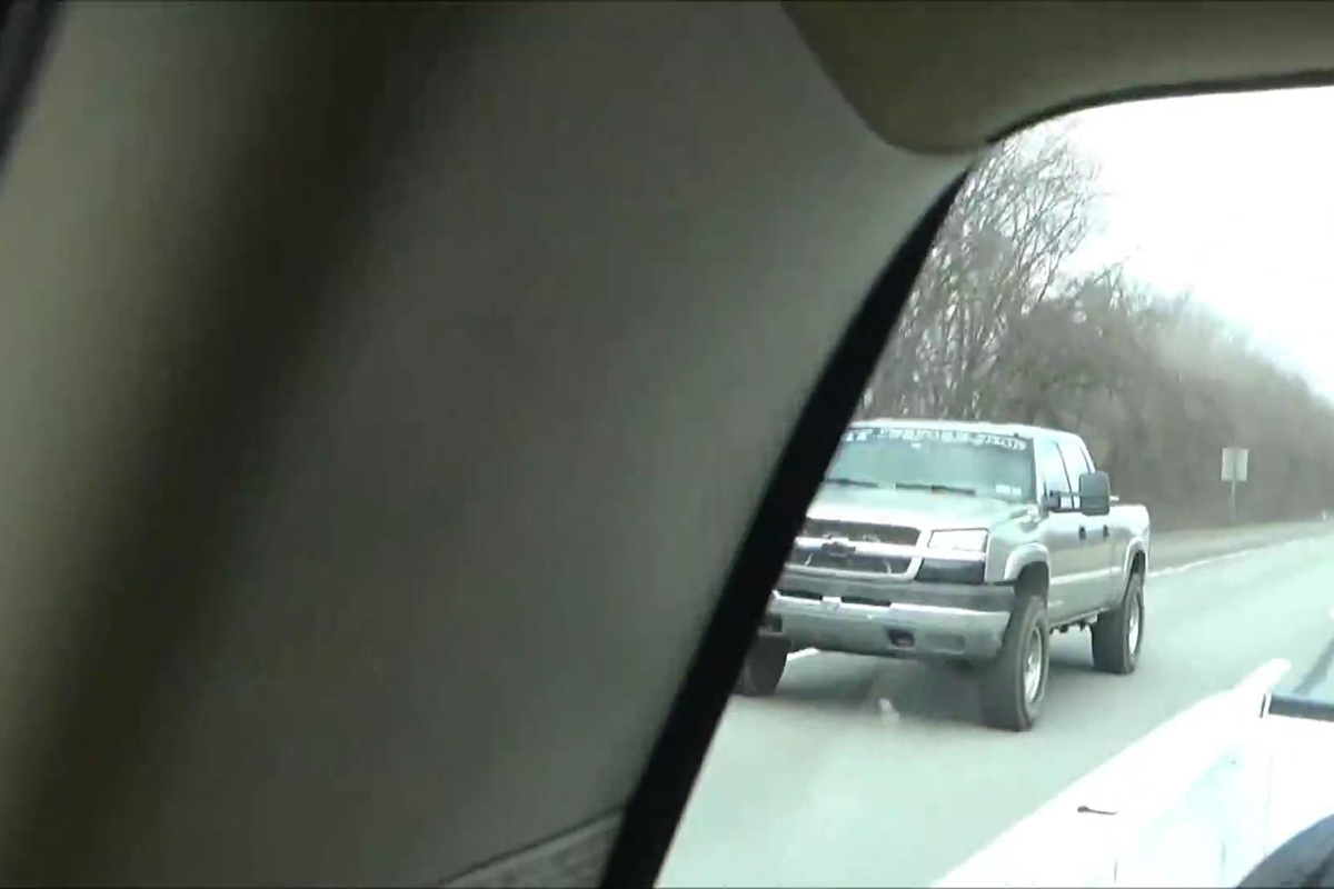
If you’re going to be driving your twin-turbo 6.0-liter LS-equipped GMC 2500 HD or Chevy Silverado on the streets, especially here in California, you’re going to need to install cats. Without mufflers, the JS Racing Products Parts Truck doesn’t sound overly loud, but it does sound mean. He did a short video showing a 10-60MPH pull that he made while he was putting together the street tune for the computer. My dad’s got a ’99 Silverado and Craig’s 2004 GMC HD doesn’t sound much louder from inside the passenger compartment.
Finishing Up the Build
The final parts of the JS Racing Products Parts Truck twin turbo build were to put the bed back on, clean things up under the hood, and put a tune on the ECU for the new engine parameters. For this Craig installed two wideband Oxygen (O2) sensors and tapped their outputs to an dual reading air-fuel gauge he suction-cupped to the windshield. This gives a better and faster reading than relying solely on the mapping software he uses.

If you don’t want to go through the hassle of setting up all the tables and the map yourself, Craig’s got links to a wide range of ECU tunes for every LS engine out there on his website. If you’re doing an LS-swap, he’s also got ECUs and wiring harness kits that are custom-made to fit your new LS engine and car. These are available for both turbocharged and non-turbocharged LS engines.
Leave a Reply