What You Need To Know About Street & Strip Driveshafts Part 3

Part 3 of Wayne Scraba’s series on driveshafts concludes with an exploration of the elements under consideration when choosing the right driveshaft for your needs.
In Part 2 of our driveshaft series, we examined different universal joints, and Mark Williams explained driveshaft balance and universal joint phasing along with the effects of driveshaft weight. We also added details on a vintage test we performed years ago on driveshaft weight. It proved rather interesting to say the least. But that’s not the end of it either. Williams notes, “There are many parameters to consider when it comes to selecting a driveshaft for your race car. These include the length of the shaft, the critical speed it will attain, the tube material type and size, the U-joint type, class requirements and budget.”
“Most important is the Critical Speed. Essentially, any rotating shaft will reach a point where it will become dynamically unstable. This leads to a “whipping” or “jump-rope” effect that causes violent vibration and ultimately leads to driveshaft failure. Critical Speed is a function of the shaft’s length, material stiffness and tubing diameter. Shorter shafts, made of stronger material, and having a larger diameter account for the highest Critical Speed potential. For example, a 52″ long driveshaft made of 3″ diameter mild steel will have a Critical Speed rating of 6,322 RPM. Make it from 3-1/2″ o.d. tubing and it’ll go to 7,322 RPM, and with big 4″ o.d. tubing 8,246 RPM is possible. Similar variations are reflected in various diameter 4130 steel, 6061 aluminum 7075 aluminum shafts. The absolute highest critical speed ratings are for carbon fiber shafts, typically found only in cars that buzz through the lights in excess of 10,000 RPM.”
Williams goes on to explain, “In order to avoid vibrations in the driveshaft, it must be operated below the critical speed. The critical speed is the rotational speed that coincides with the natural vibration frequency of the shaft. At this speed the shaft becomes dynamically unstable and vibrations are likely to occur. The critical speed of a MW driveshaft can be determined given the driveshaft length.”
The following chart (“Table 1”), courtesy of Mark Williams lays out the critical speeds of various different driveshafts, in various different lengths:
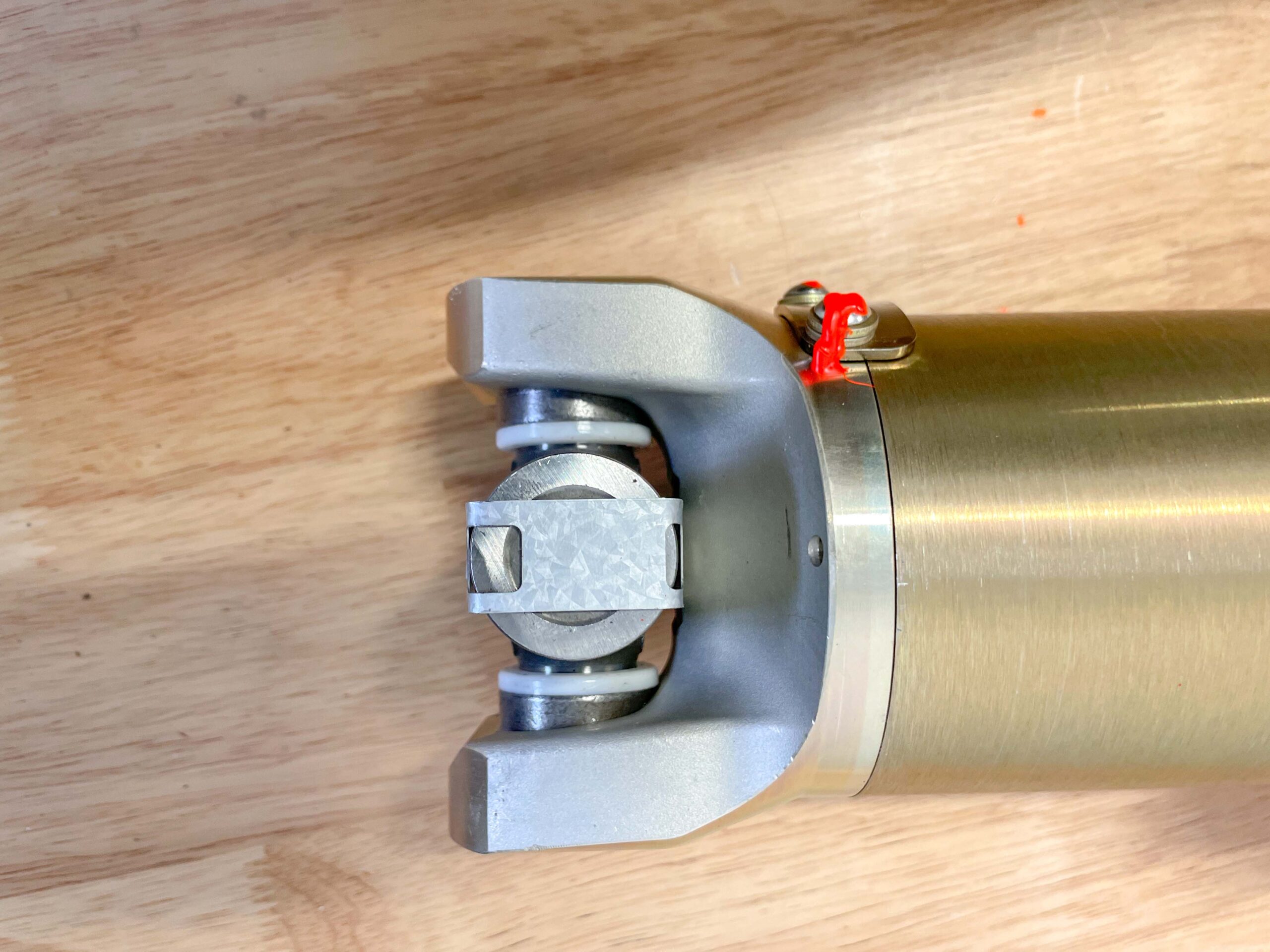
Universal joint operating angle is also very important. Excessive operating angles can lead to driveshaft and universal joint failure. Mark Williams notes that while the driveshaft allows for movement of the rear end there are also important operating angles and shaft length criteria that you must adhere to. If these limits are exceeded, it can lead to driveline vibration and/or failure, transmission damage, and it can also reduce the amount of power being transmitted to the rear wheels.
According to M-W, “In a perfect world the centerline of the transmission output shaft would be exactly parallel to the pinion centerline on both vertical and horizontal planes (but not “pointed” at each other). But for most applications, there will be some offset. Centerlines should be parallel, within 1/2 of a degree (see diagram below), the operating angles of the front and rear U-joint would be the same. The combined angles should not exceed 5 degrees.
“A simple method that can be employed to ensure that the trans output shaft and pinion are parallel is to place a digital angle finder on a machined surface of the engine block (i.e. oil pan rail etc.). Using a floor jack, raise the front or rear of the car as needed to bring the angle finder to zero (note: if the rear needs to come up jack under the housing). Then place the angle finder on the face of the pinion yoke. If this angle is anything but zero, the pinion angle must be adjusted to bring it to zero. See Figure 1 below:

“Driveshaft length is also very important. The function of the slip yoke is to compensate for suspension movement. A shaft that is too long can bottom-out the slip yoke in the trans, causing damage. A shaft that is too short doesn’t provide the yoke needed support and has potential to bind. The shorter the shaft (4-link dragsters in particular) the more likely this can occur.
“To properly determine optimum driveshaft length, it’s important that the car is on the ground with the suspension set to racing conditions and all weight should be in the car, including the driver, when measuring. The technicians at Mark Williams Enterprises like to get as much information as possible, so that measurements can be cross-referenced to assure accuracy.”
To help you with that, we’ve attached a form Williams uses to determine proper driveshaft length. According to M-W, “Driveshaft length is also very important. The function of the slip yoke is to compensate for suspension movement. A shaft that is too long can bottom-out the slip yoke in the trans, causing damage. A shaft that is too short doesn’t provide the yokes needed support and has potential to bind. The shorter the shaft (4-link dragsters in particular) the more likely this can occur.”
The following dimensions are required for a custom driveshaft. Keep in mind, you don’t need all of the dimensions, but the more, the better:
A. End of trans yoke to end of pinion yoke
B. End of pinion yoke to U-joint center
C. U-joint center to U-joint center
(make sure that your measurement includes 3/4″ to 1″ of slip)
D. End of trans yoke to U-joint center
E. Transmission seal to U-joint center
(most common & easiest to measure)
F. Trans seal to pinion seal
G. Trans seal to end of output shaft”

In the end, it’s not difficult to see that while a driveshaft is out of sight, it shouldn’t be out of mind. There’s clearly much more here than meets the eye and its also clear Mark Williams is well ahead of the curve when it comes to driveshaft technology. For a closer look, check out the accompanying photos, charts and graphs.