Braking Point: The Ancient Art Of Rebuilding Drum Brakes Part 2
Wayne Scraba
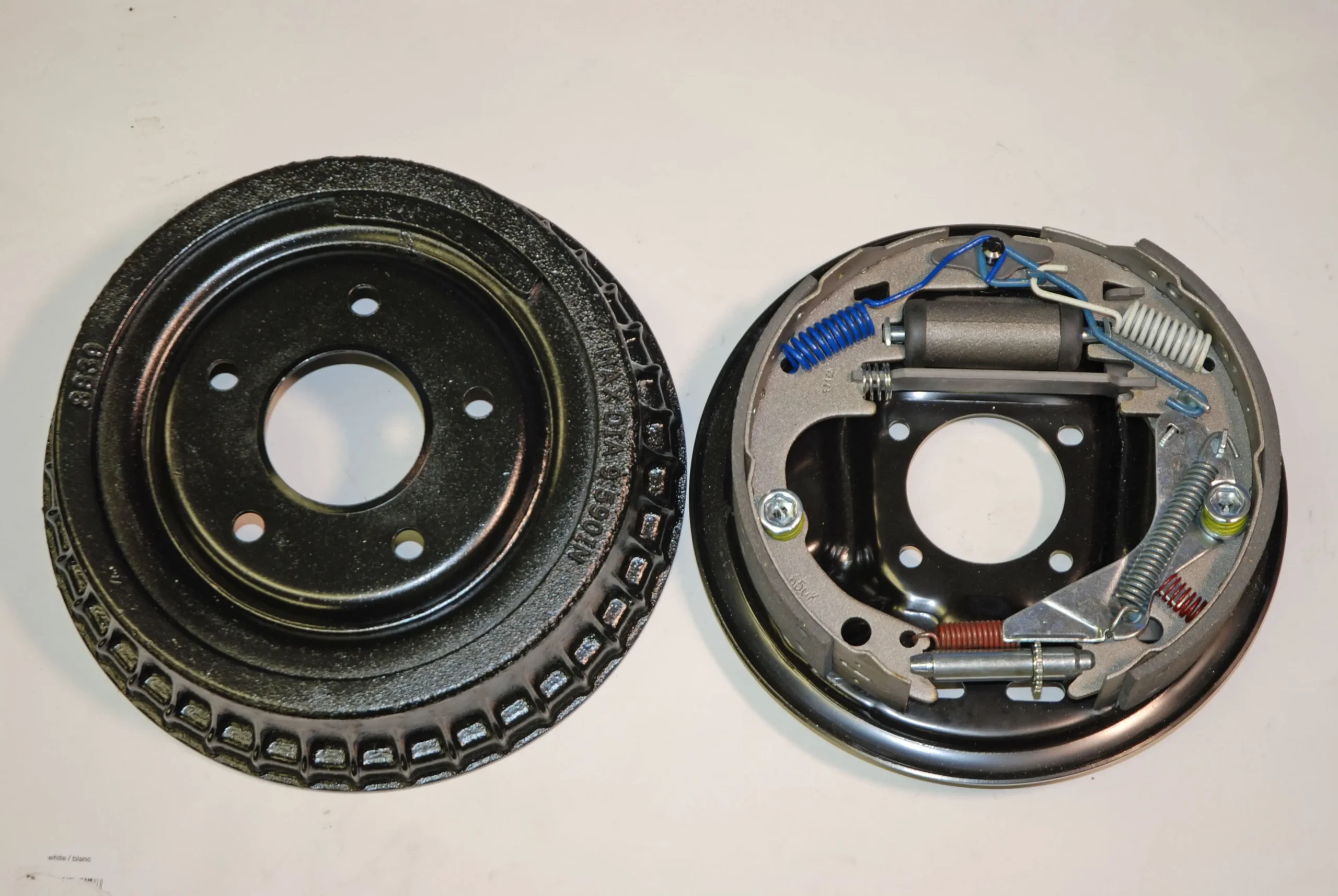
Click Here to Begin SlideshowIn a past issue, we dug into the basics of rebuilding a set of drum brakes. Why drums? Simple. A large percentage of vintage US-built cars and light trucks came standard with drum brakes on at least one axle – some with drum brakes on all four corners. When it comes to rebuilding drum brakes, you’ll have to deal with shoes and small parts kits (sometimes two kits per side). Unlike disc brakes, there tend to be quite a few pieces included. With the sheer number fiddly little pieces involved and dealing with considerable spring pressures, it sounds like a monumental task. At least at first glance. But when you get into it, you’ll find it’s really not that difficult. Just take your time.
We used a vintage GM drum brake assembly in the accompanying slide show -- most North American drum brakes work and assemble in a similar manner. Check it out as we finish the brake job:
Click Here to Begin Slideshow
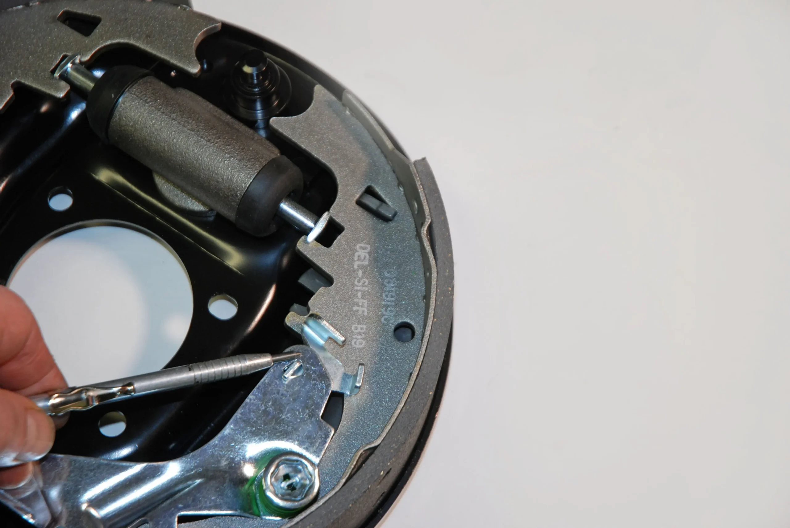
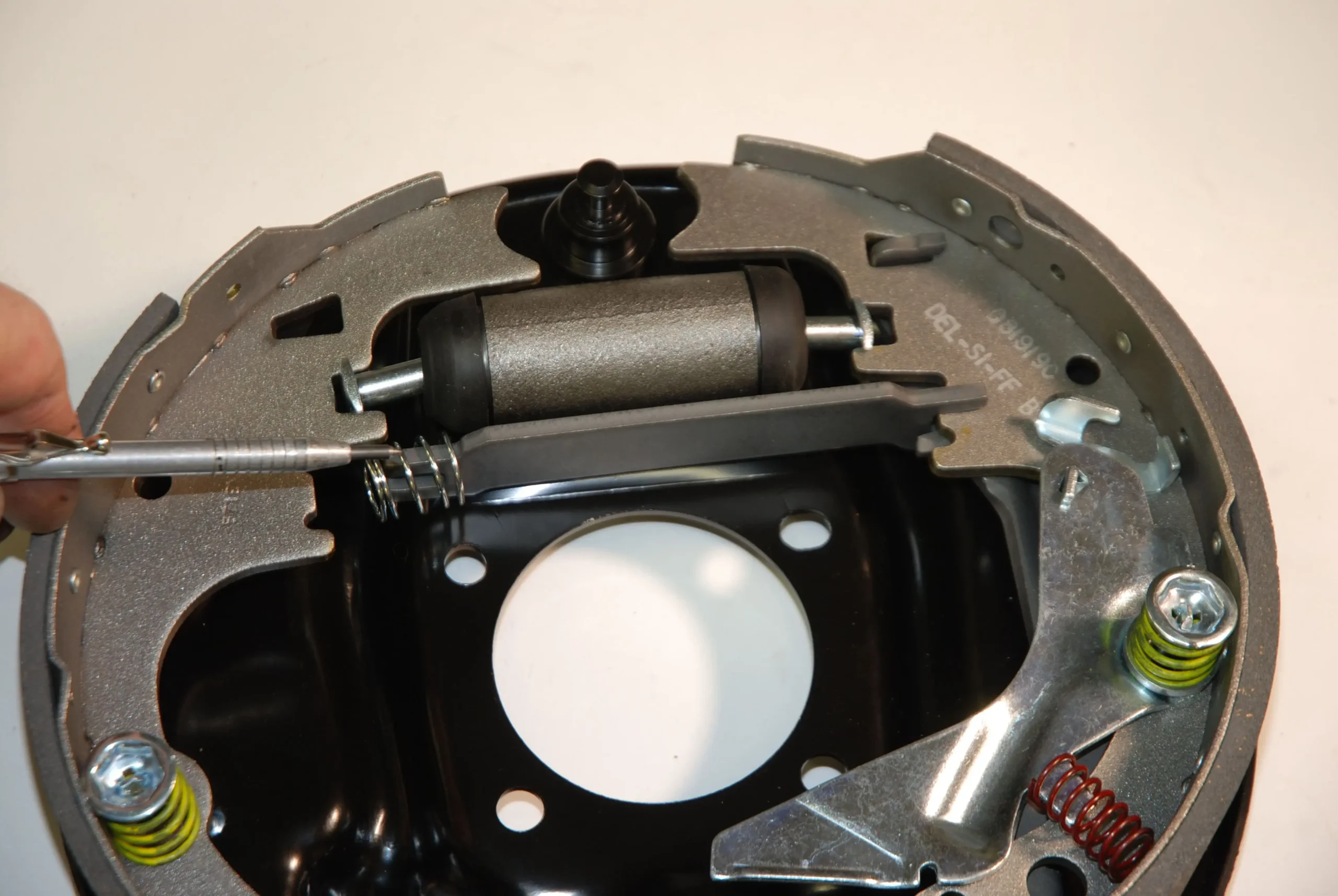
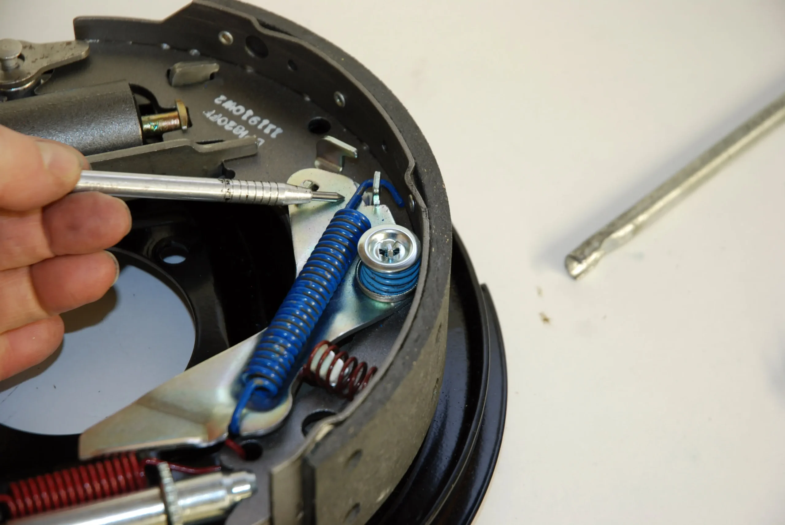
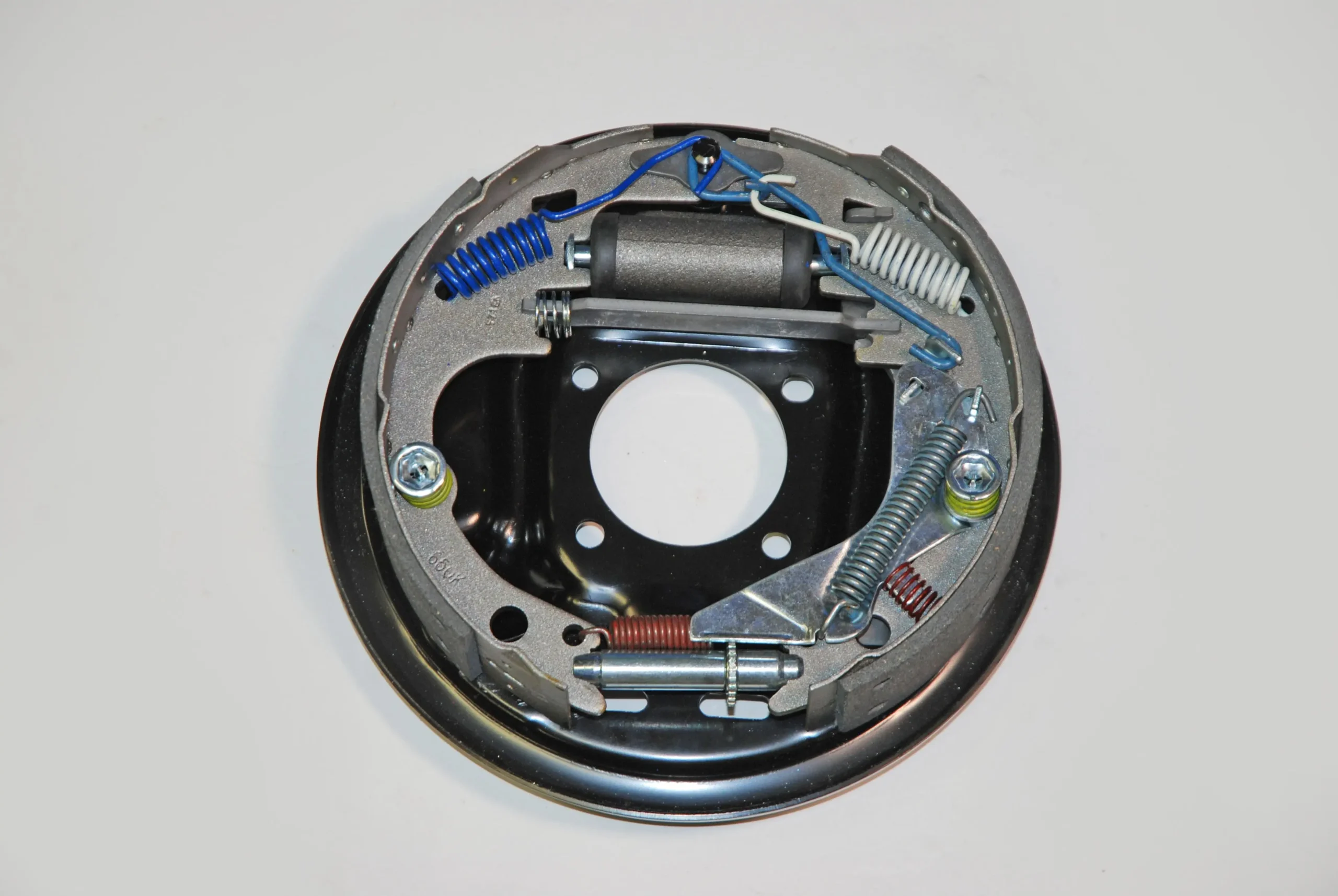
The self-adjuster actuator lever is located on the face of the trailing (back) shoe. Examine the actuator lever closely. You’ll find there is a small secondary hook that slips into place. That hook or “pawl” is for the return spring (more on this later), however it must be installed now. You cannot install it later!
The coil spring used for the actuator differs from the one found on the leading shoe. In this case it’s a flat bottom example that mandates a spring seat.
The spring seat installs in the actuator lever like this. It’s followed by the spring and retainer.
: The coil spring tool is used to compress the spring while the nail is held in place. Seat the nail in the retainer.
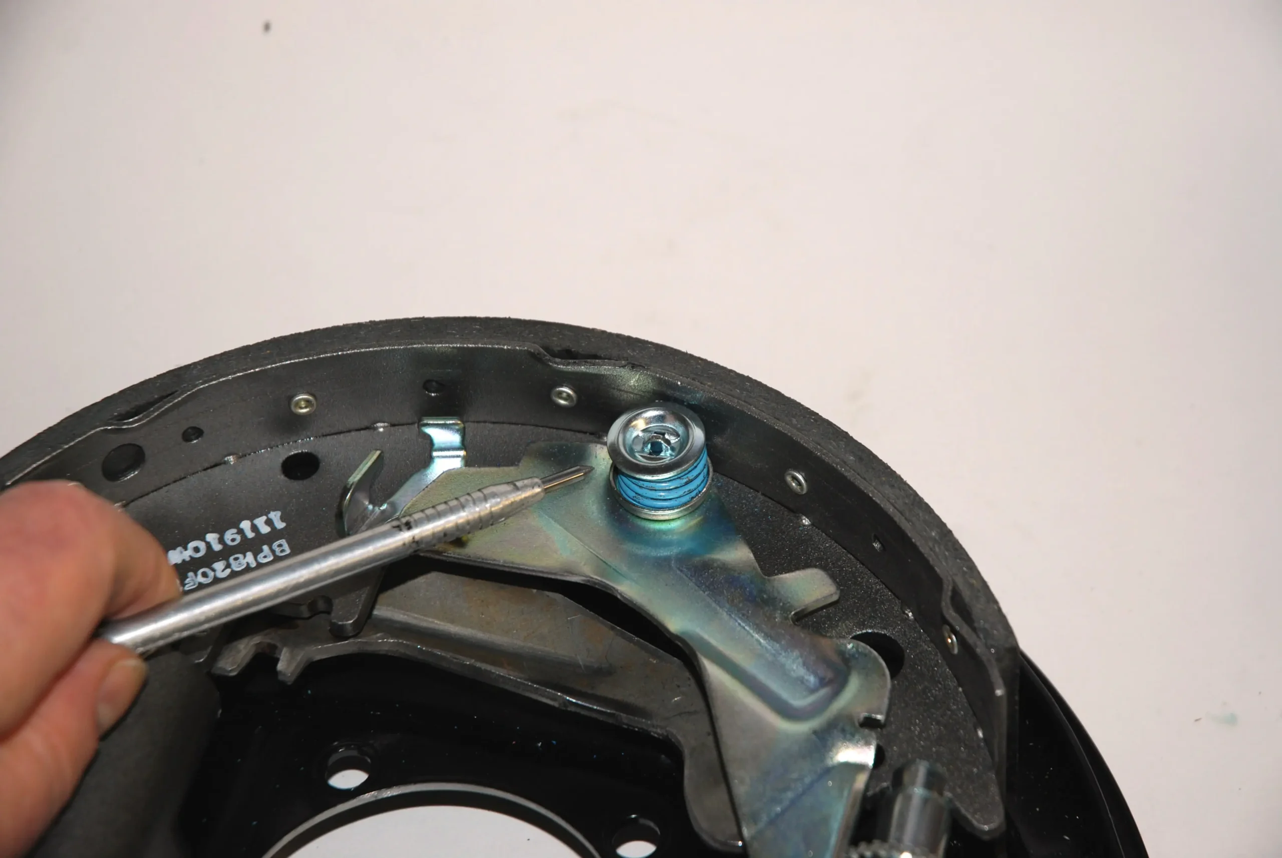
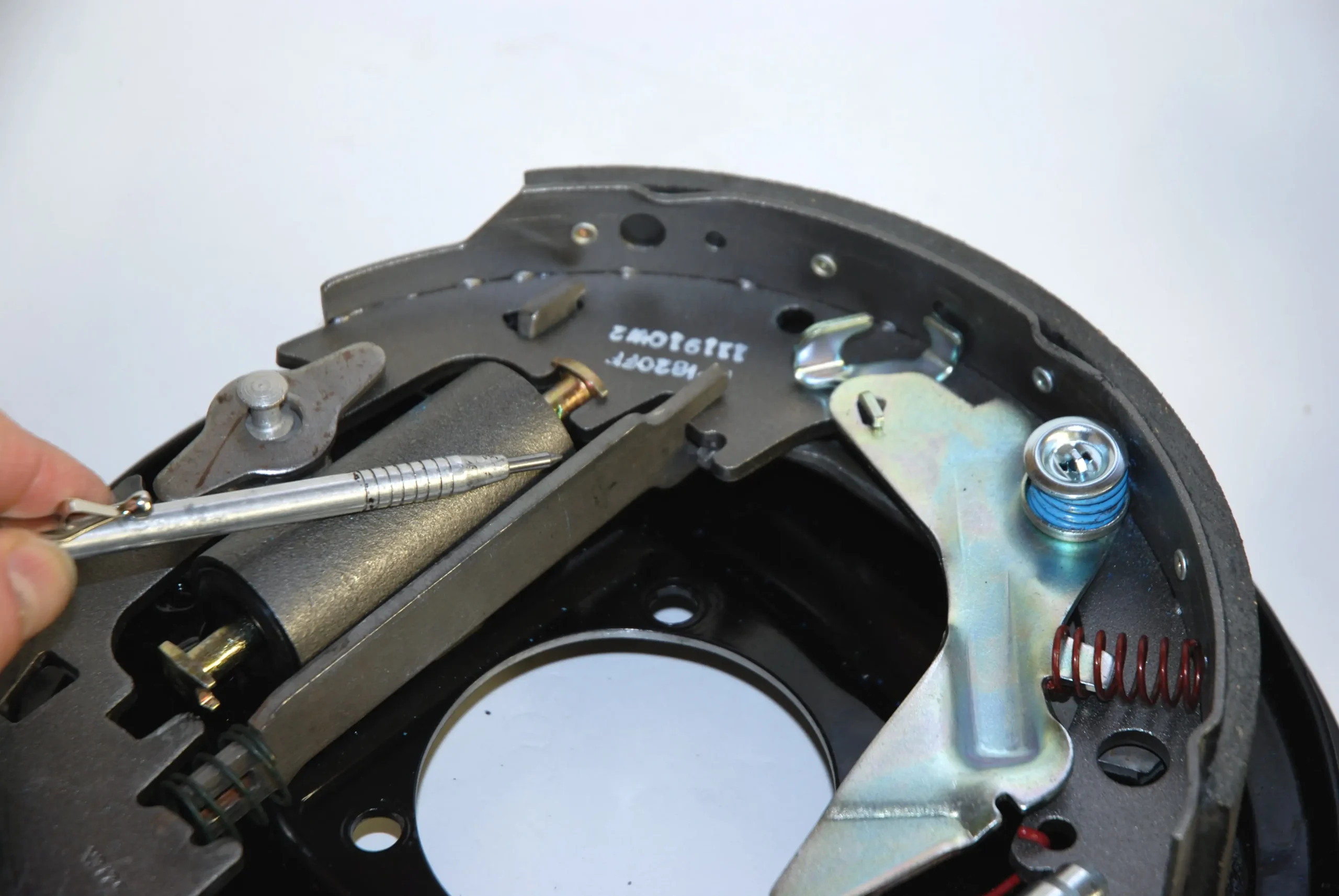
Note the flange on the actuator? This is where the small bumper spring locates. It simply slips into place. Once the other springs are in place, the bumper spring will be kept under tension.
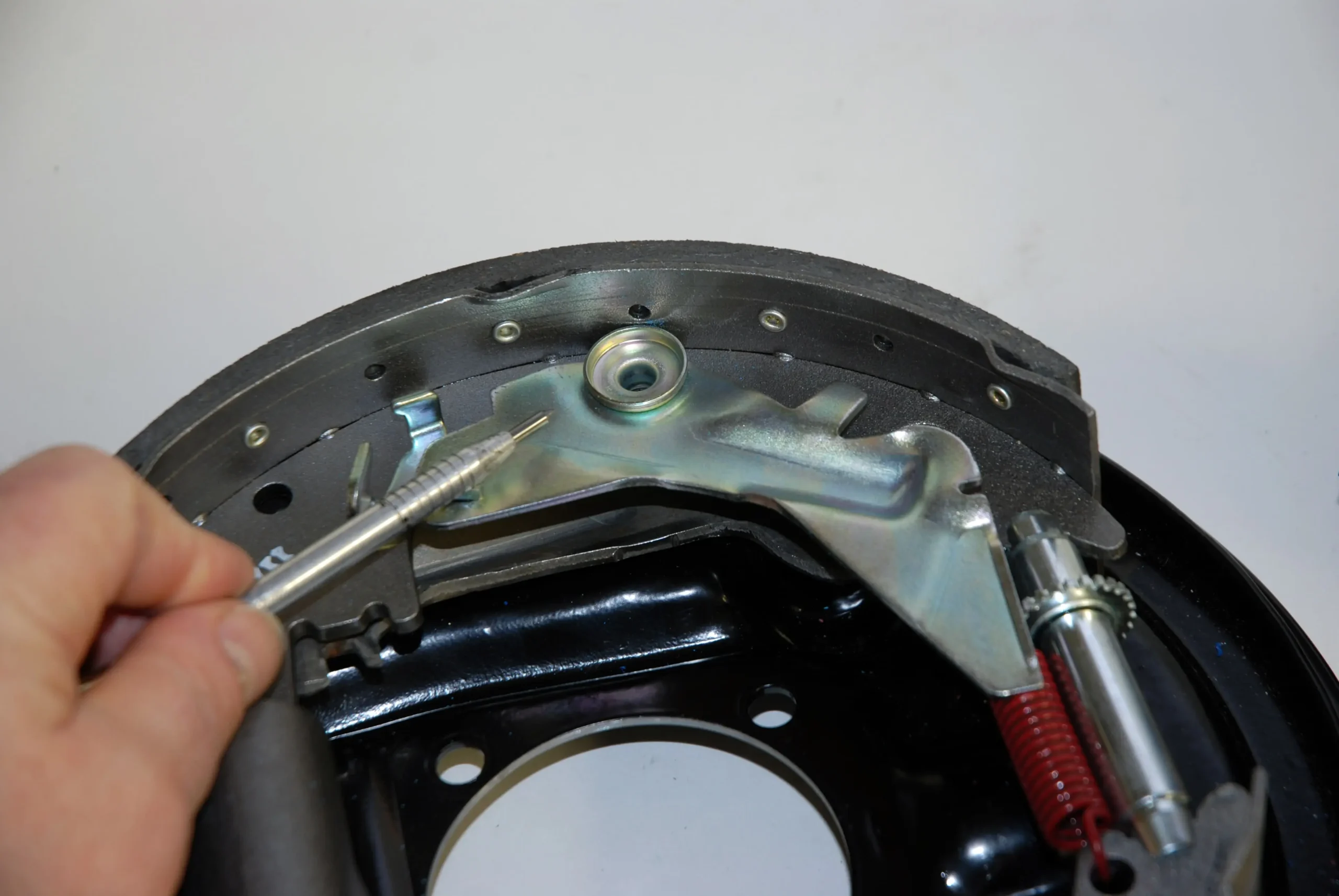
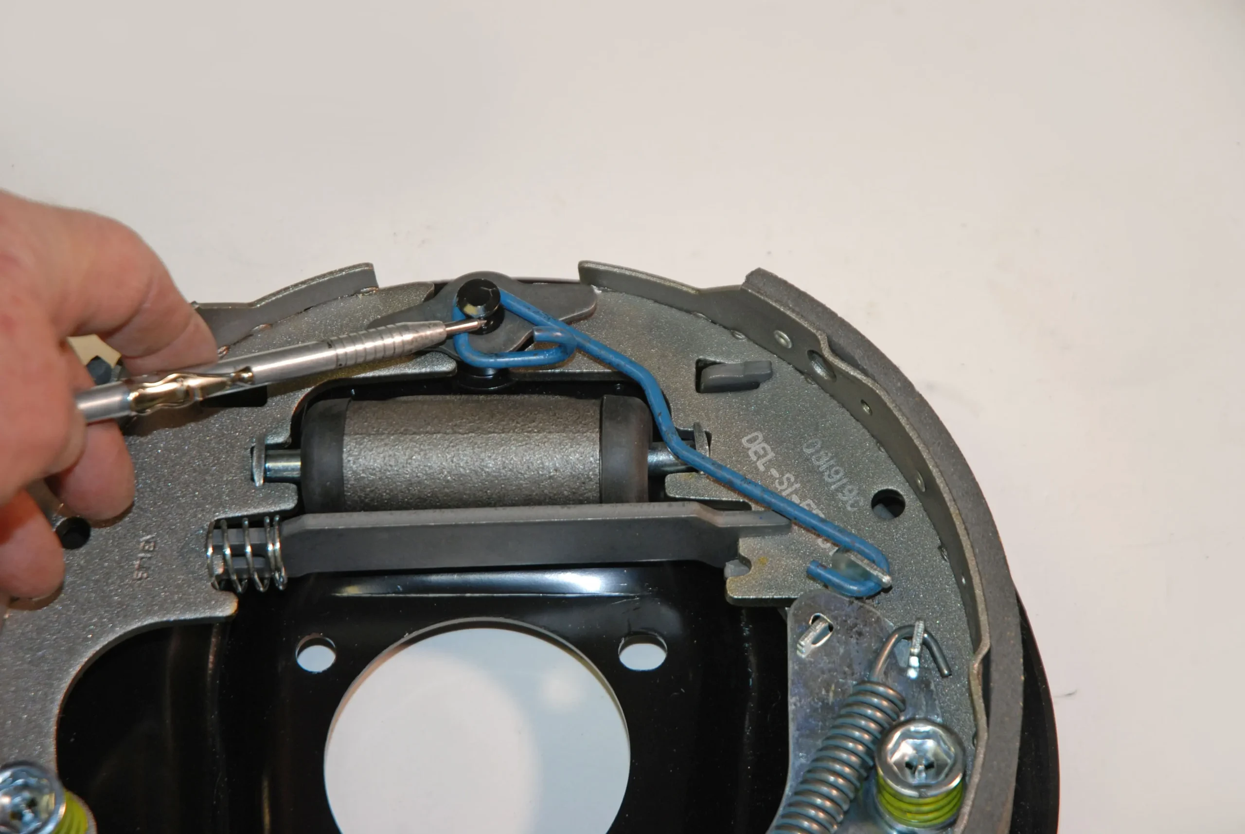
The park brake strut is the next piece to be installed. You may have to re-use your existing strut (some kits don’t come with them). Note the spring at one end. It only fits on the leading shoe.
During the installation process, slide the strut into the trailing shoe first. You’ll note the slot in the strut also engages the park brake lever.
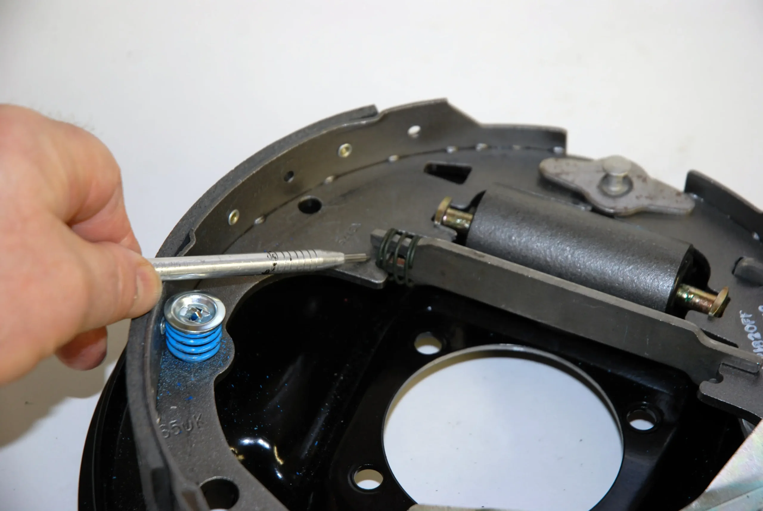
Spread the shoes apart slightly and install the sprung end of the strut into the primary shoe. Slide the shoes back together.
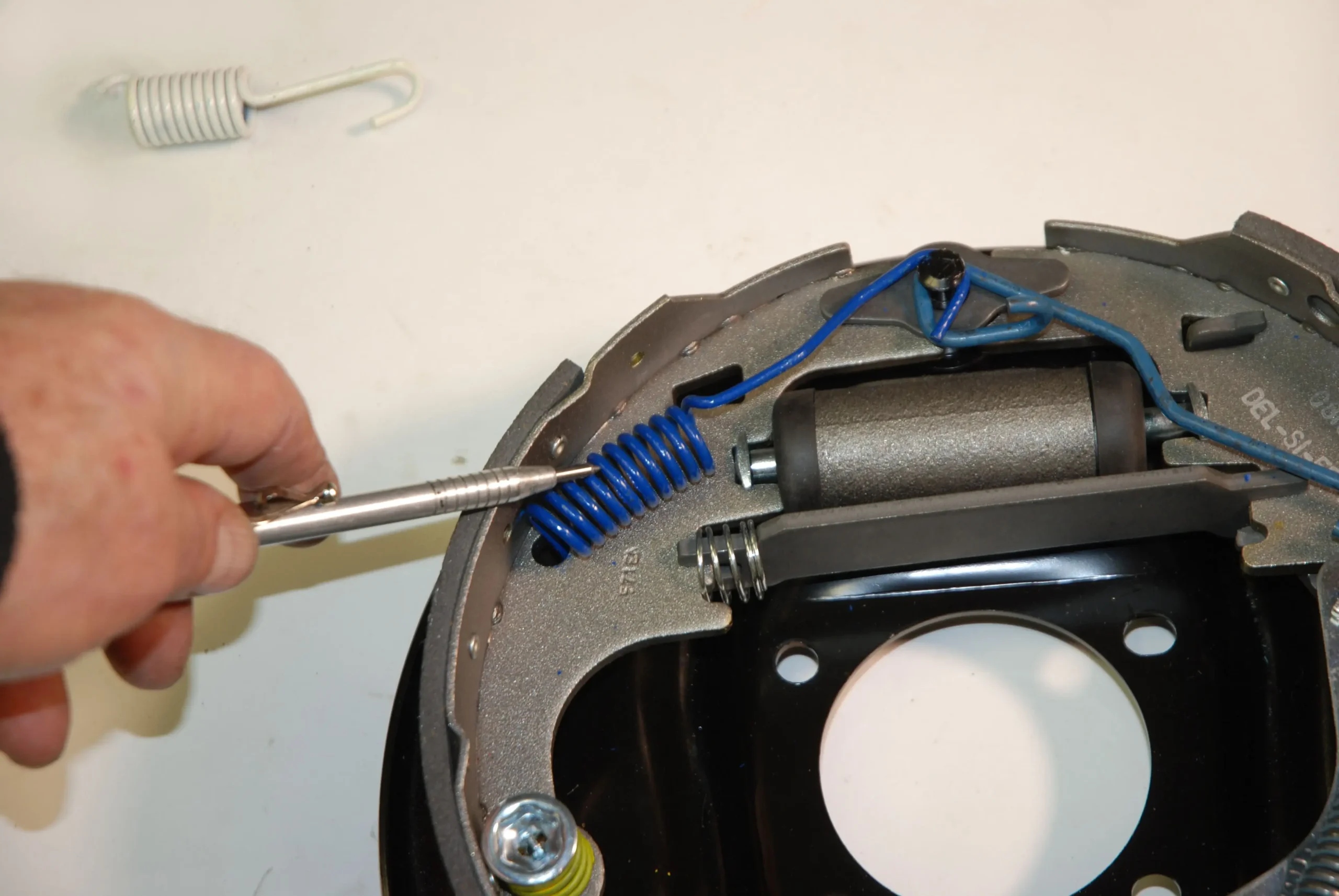
Next up, install the actuator pull-back spring. It’s easier to install the lower hooked end first. With one end of the brake pliers handle inserted through the spring eye stretch the spring out and over the tab on the pawl. The idea is to lever the spring body in place and guide it with your free hand (gloves are definitely a good option!). The actuator lever body is designed with a recess for the spring body. The spring only installs one way.
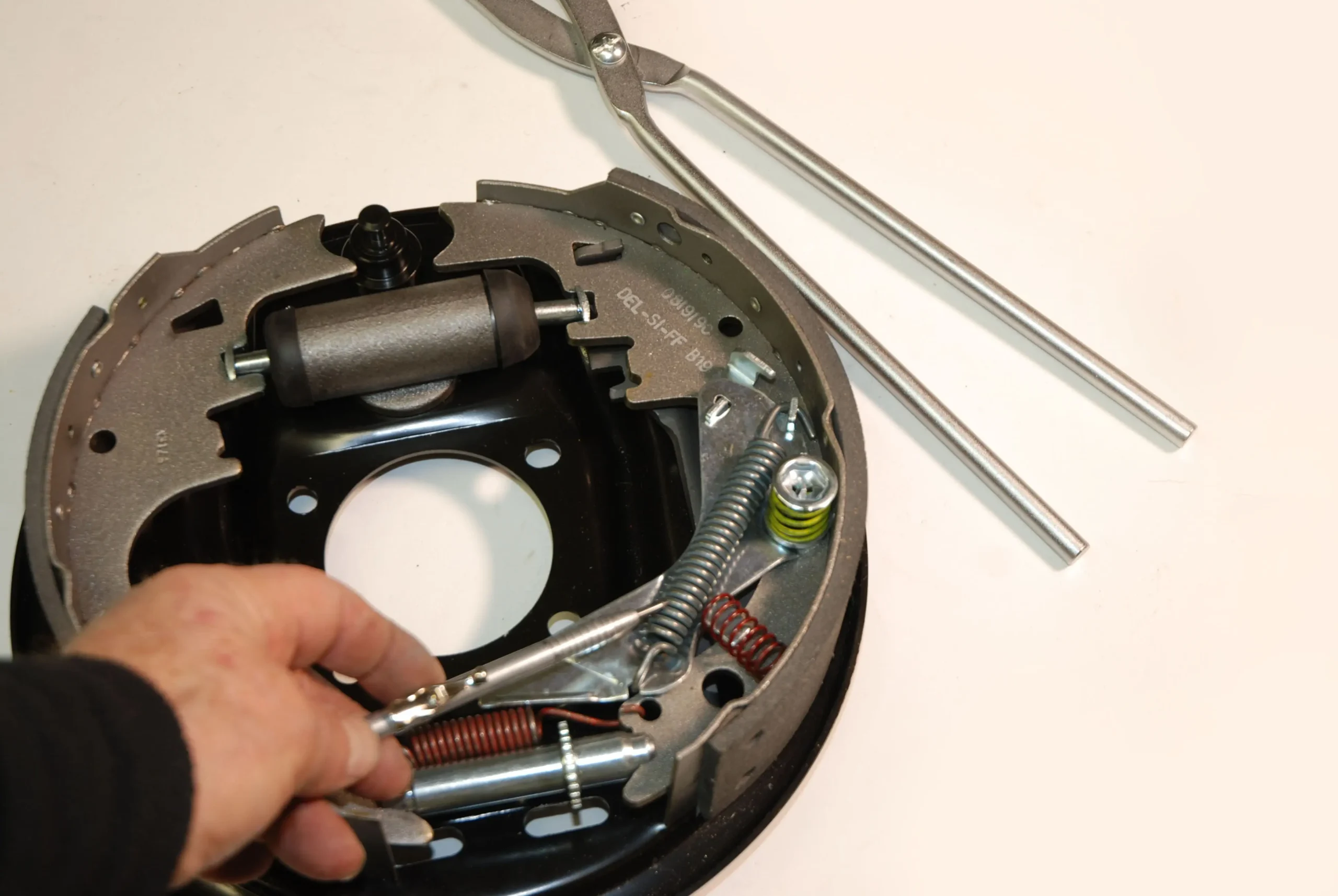
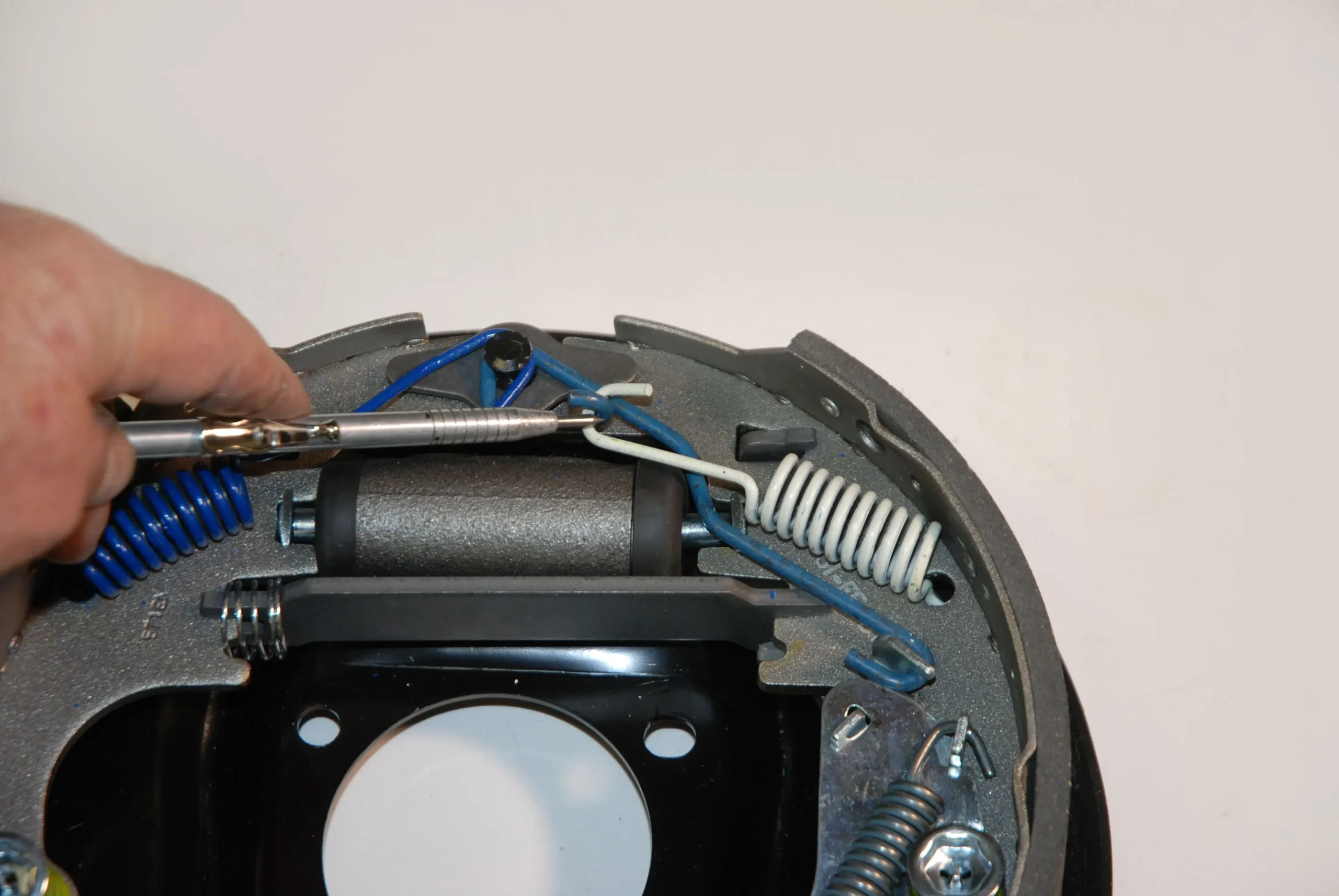
The link for the actuator installs next. Insert the anchor guide over the anchor pin. Hook the actuator link to the pawl as shown here.
If the shoes are pushed tight at the top (at the anchor), its sometimes possible to slide the other end of the link over the anchor. If not, use the brake pliers to slide it over the pin.
Install the leading shoe spring next. Hook the shoe end in first, and then, using the pliers, work the spring over the anchor pin as shown here (using the same “levering” process mentioned earlier).
The trailing shoe spring is the final piece in the backing plate puzzle (aside from the park brake cables). The spring must be attached to the shoe first, but instead of hooking directly to the anchor pin, the opposite end attaches to the open end of the actuator link.
Here’s the finished product. It’s not a super-difficult job and it’s something you can definitely do yourself with the right collection of parts and of course, the right tools.