Click Here to Begin Slideshow
Up until the mid-70s to the mid-80s, leafspring rear suspensions were where it was at for muscle cars. Problem is, leafsprings have serious drawbacks. Stick a big, torquey motor under the hood with a strong transmission and, no matter how much money you put into the rear suspension, you’re still going to have the drawbacks of a leafsprung rear end.
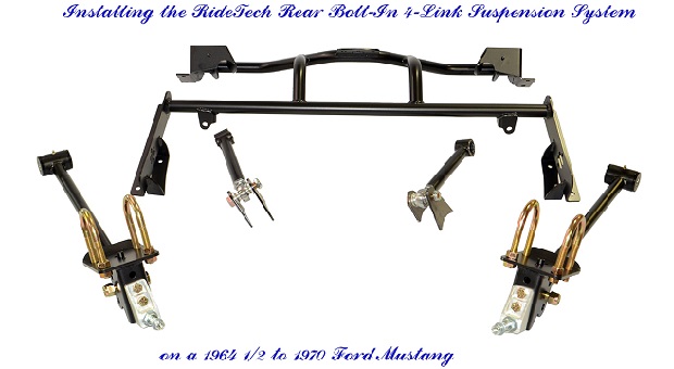
All that engine and trans money was spent with one reason in mind: Getting down the track as quickly as possible. The problem is that leafsprings tend to want to unload when you tromp on the pedal at the light; they don’t want to allow every bit of torque being sent to your rear wheels to be transferred to the ground. They want to bend and induce wheel hop. You can almost completely eliminate wheel hop by removing those leafsprings and installing a quality 4-link rear end like Ridetech’s “Bolt-On” (some welding required) 4-Link kit. The major drawback of this kit is that you have to buy the Ridetech Shockwaves or coilovers separately.
You will need a hammer to make sure the cradle is properly installed. A regular hammer with a metal head will damage the cradle, so it’s recommended that you use a dead blow hammer like this one.
Image credit: Armstrong Tools
RideTech calls their 4-Link Rear Suspension package for the 1964 ½ to 1970 Mustang a bolt-on kit. However, that isn’t completely true. There are four tabs that will have to be welded onto to your axle tubes/rear end housing. Everything else does just bolt on. Other than a decent quality welder, most tools you’ll need for this project are fairly commonplace.
• Jack and jack stands (preferably four, but you can get away with two)
• Drill
• Three drill bits up to ½ inch or a Unibit/stepper bit
• Socket set with ratchet and extensions
• Wrench set
• Lug wrench
• Torque wrench
• Impact gun with lug nut socket (Recommended but not required)
• Impact sockets (if using an impact gun)
• Two to four large C-clamps
• Dead blow hammer
• Sandpaper or wire wheel or other abrasive
• Marking pen
Be sure the location you choose for this project is a level surface and not your driveway.
The exhaust, brake and fuel lines will get in your way during the installation, so you’ll need to get them out of your way. The brake and fuel lines don’t have to be disconnected, they just need to have their brackets/clips removed; then, carefully push them out of your way.
You‘ll be installing new shocks, so the old ones need to go. This kit only works with Ridetech’s Airwave shocks or coilovers.
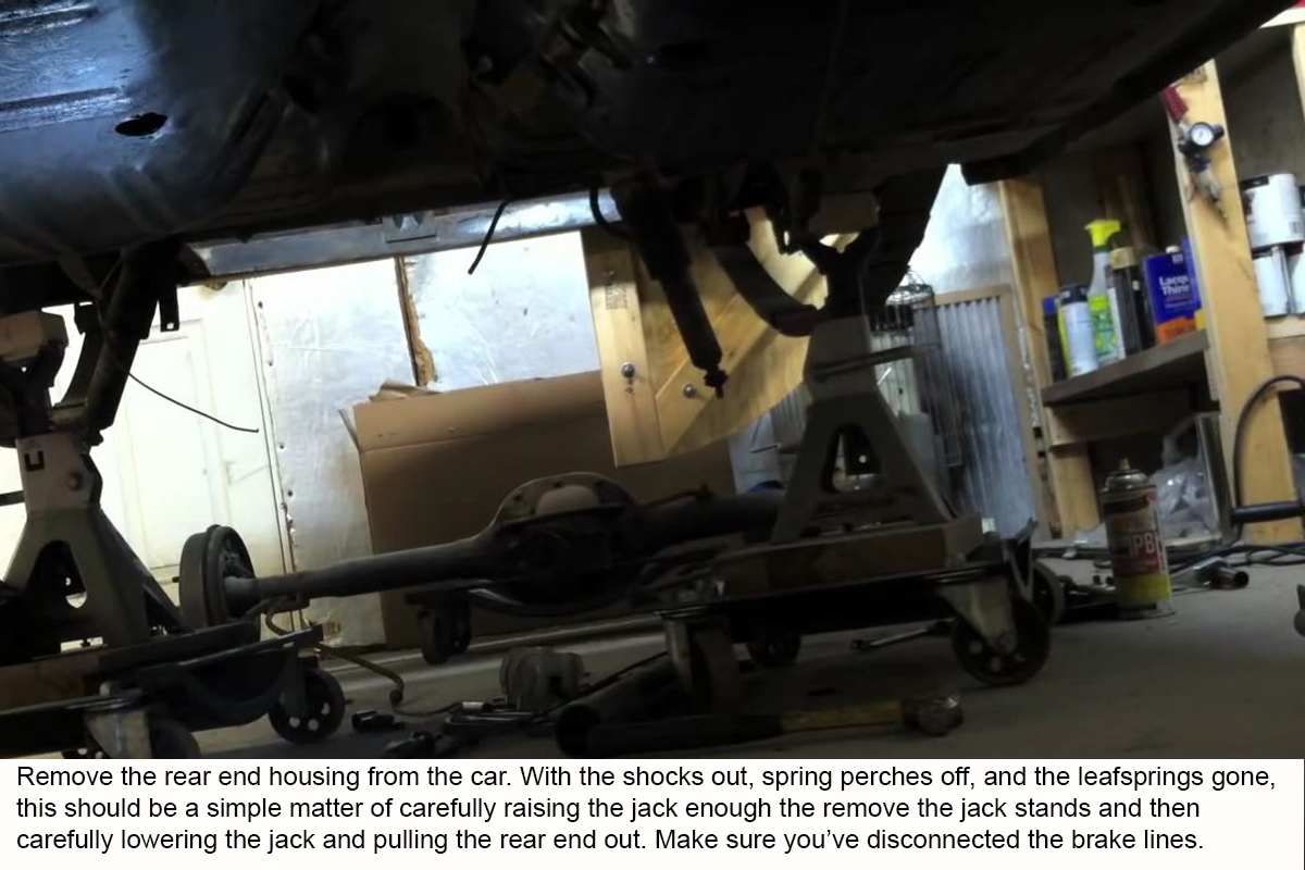
The driveshaft should be dropped before you remove the leafsprings, because sometimes the nuts on the U-bolts need a little “convincing” to break loose, and you don’t want the rear end shifting around on you.
Leafspring removal is a two-step procedure for both sides. First to come off are the two spring perches/lower shock mount brackets, followed by the removal of the leafsprings themselves. Sometimes a clip that holds the parking brake cable can be found on the leafspring in front of the axle. This will need to be popped off before the springs can come out.
You won’t need the leafsprings after this installation. I would save them, along with the stock spring perches, just In case you decide to sell the car or bring it back to stock condition.
Once the rear end is out, I recommend spraying it down thoroughly with a degreaser or other cleaning agent. Pay special attention to the three to five inches on either side of the center section, because you’ll be welding there a little later.
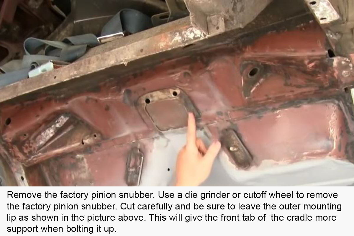
The factory pinion snubber is right where the front center of the cradle needs to be bolted up, so it has to go. I would recommend taking the time right now to give the area back here a good and thorough cleaning and then a few coats of primer and paint. Your car may or may not have two holes in the plate as shown in the image above. Most won’t.
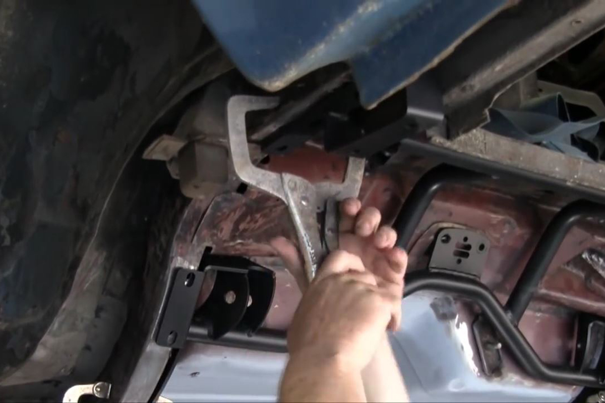
Loosely thread the two bolts through the holes in the cradle and into the bolt holes where the pinion snubber was. Use four large C-clamps to secure the cradle in place and then smack it to make sure it is properly seated on the frame rails. Next, mark the locations for the seven pairs of holes on the bottoms of the frame rails, plus the two sets of three in the sides of the frame rails up front.
Make sure your fingers are clean and dry when doing this, or the U-bolts might slip and fall or get stuck inside the frame rails.
Go easy on this step. Don’t just slam the cradle back up under the car or you’re going to lose at least one of the U-bolts. Carefully guide the cradle over those bolts and be quick about getting the Nylocs on them as they slide into their holes in the cradle. Don’t forget flat and lock washers on each. The 3/8 inch self-tapping bolts go into the 5/16 inch holes you drilled in the sides of the frame rails.
This can be done with the rear end unit under the car or on a work bench.
Be sure to start off by installing these in the two lowest holes in the bracket. You can adjust them later if you need to.
There are three bolts that can be used to install the lower links, depending on which year Mustang you’ve got. All model years use the 5/8 X 2 ¾ inch bolts with the thin 5/8 inch Nylocs on the axle mounts, whereas 64-67 Mustangs need to use the ½ X 6 inch bolts and Nylocs and 68-70 Mustangs need the ½ X 4 ½ inch bolts and Nylocs.
‘Pinion angle’ describes the angle between the driveshaft and the pinion.
Image credit: RideTech
Ride height should leave about 4 ½ inches between the bottom of the frame rail and the top of the axle housing. It’s recommended to cut two pieces of wood or steel, sit them on top of the axle and then raise the whole rear end until these dowels are firmly sandwiched between the axle housing and frame rails.
This image oversimplifies pinion angle greatly. It shows too much of an offset between the height of the transmission output shaft and the differential, which creates too much of an angle on the U-joints to work properly. The angle between the driveshaft and the pinion should be no more than ten degrees (10º), with between zero to five degrees considered ideal.
Leave the bolt on the differential tabs loose for now.
Note the 4 ½ inch long piece of all-thread in the image being used to maintain ride height as well as pinion angle. Note it is welded to both the bottom of the frame rail and the top of the axle tube.
Don’t tighten the jam nuts on the links just yet. You still have to do a final setting of the pinion angle.
The designed ride height of the Ridetech Coilovers/Shockwaves is 14 ½ inches from the center of the upper mounting lug to the center of the lower mounting lug.