

![[Gallery] Road Rats Car Show](https://www.racingjunk.com/news/wp-content/uploads/2022/05/2A-e1651770667920-376x206.jpg)


How and Why to Adjust a Holley Carburetor Accelerator Pump
Photos Via Holley
How many times have you seen or heard a car try to take off when the light goes green, and for some unexplainable reason, it hesitates, or worse, stalls? The reason might not be unexplainable, and nine times out of ten it is caused by a simple adjustment being out of adjustment.
In order to get a stock or mildly modified engine to accelerate smoothly, when you push down on the accelerator pedal, you typically need both an advance in ignition timing and an increase in fuel delivery. In a stock or mildly modified street machine, the distributor vacuum advance senses when you open the throttle and then provides additional timing advance that is required. But it is the duty of the accelerator pump on your carburetor to provide the momentary increase in fuel flow.
The accelerator pump circuit(s) in a Holley carburetor acts to smooth the transition between the idle circuit and the main circuit. When properly adjusted, there will be no hesitation or stumble when the throttle is opened. In operation, the accelerator pump is connected by a linkage to the throttle butterfly shaft. When you accelerate, the accelerator pump squirts a spray of fuel directly into the throttle bores of the carburetor. This overcomes the momentarily lean condition by adding a shot of extra fuel.
Differences in vehicle weight, transmission, and rear axle ratios will affect how much fuel along with the delivery rate of the fuel that must be provided by the accelerator pump. Given these factors, there’s a good chance you’ll have to tune the accelerator pump circuit to fit the needs of your vehicle. A straightforward series of adjustments can sort out the accelerator pump circuit(s) in your Holley carburetor:
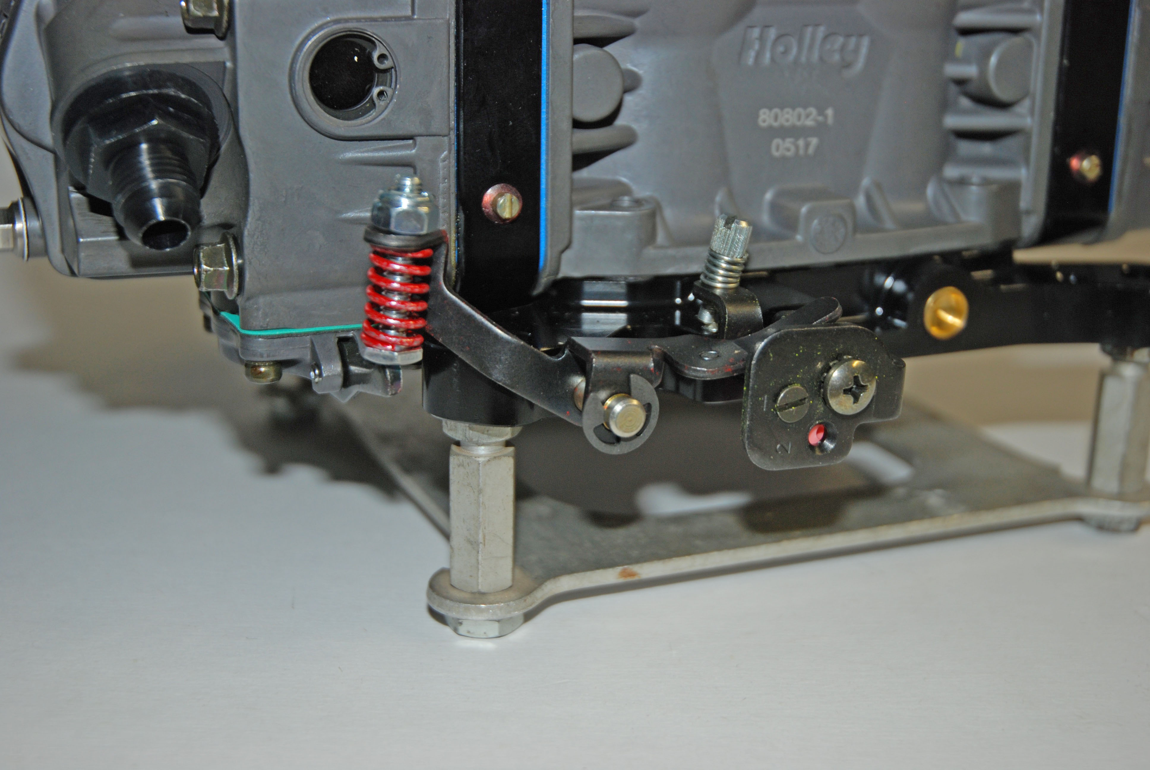
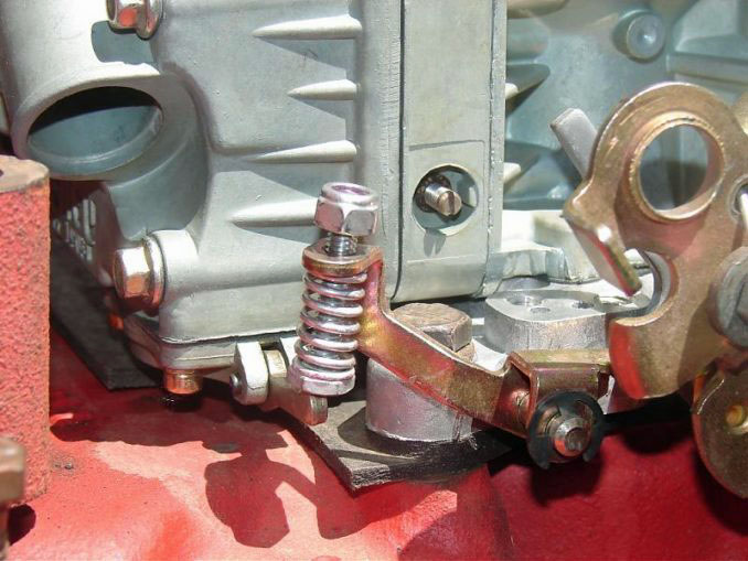
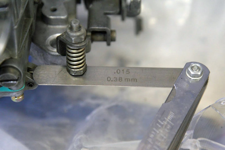
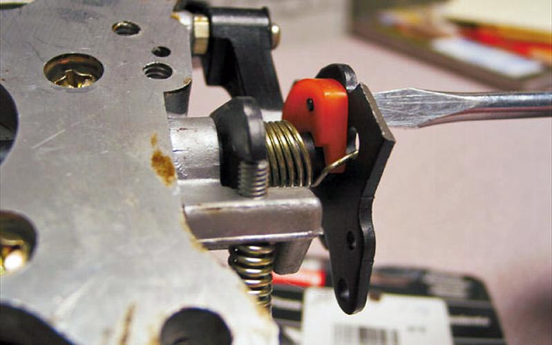
On a Holley carburetor, the accelerator pump is located on the bottom of the float bowl. The accelerator-pump system consists of three main components: the pump diaphragm, the pump cam, and the pump nozzle (“squirter” or “shooter”). If your car is experiencing a stumble, begin by first checking the clearance between the pump operating lever (beneath the screw and spring) and the pump diaphragm arm. Do this at wide-open throttle (with the fast idle cam disengaged); the clearance should be approximately 0.015-inch. If there is too much clearance (or conversely, not enough clearance), hold the screw at the bottom and adjust the nut at the top of the spring. Double-check the clearance (with a feeler gauge) at wide-open throttle. If the clearance is correct, you’ll see the pump arm move down as the feeler gauge blade is inserted. When you remove it, you’ll see the arm move back up a bit. The reason for the clearance is to ensure the pump diaphragm is never stretched to the maximum limit at wide-open throttle. Next, you will want to make sure that the accelerator-pump arm starts to move simultaneously with the throttle.
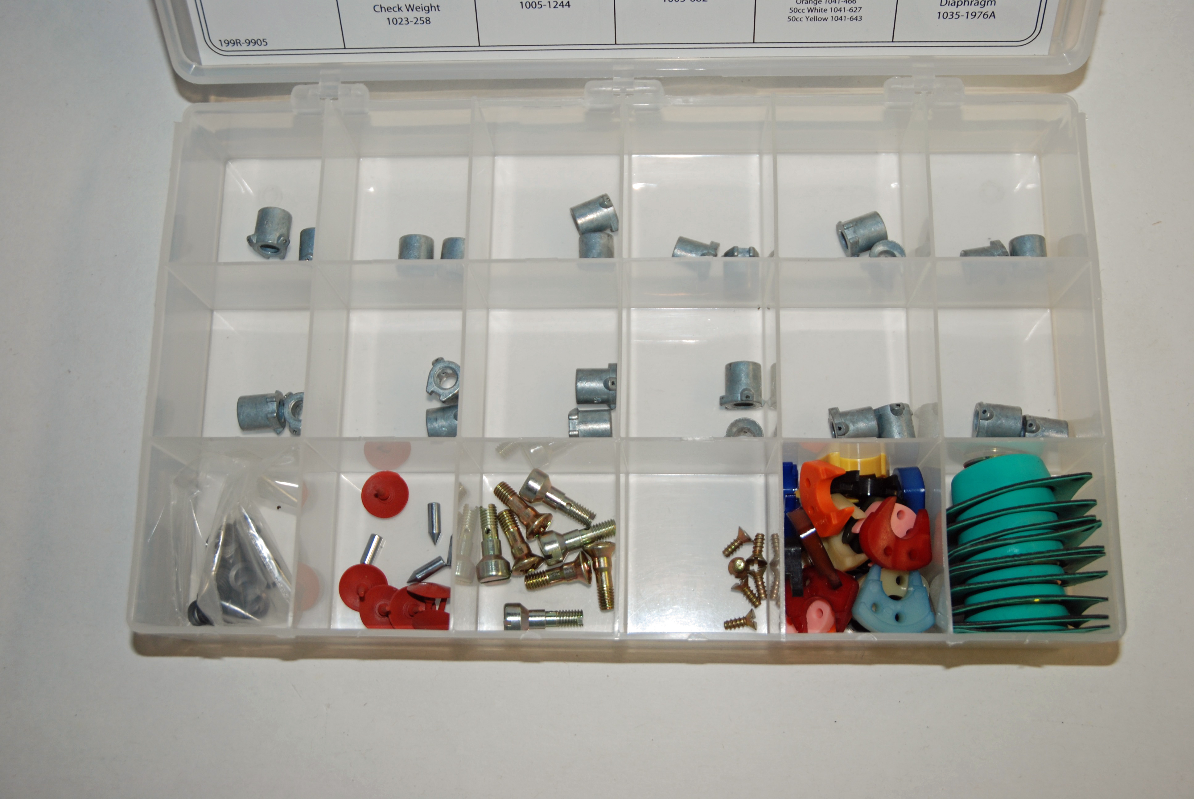
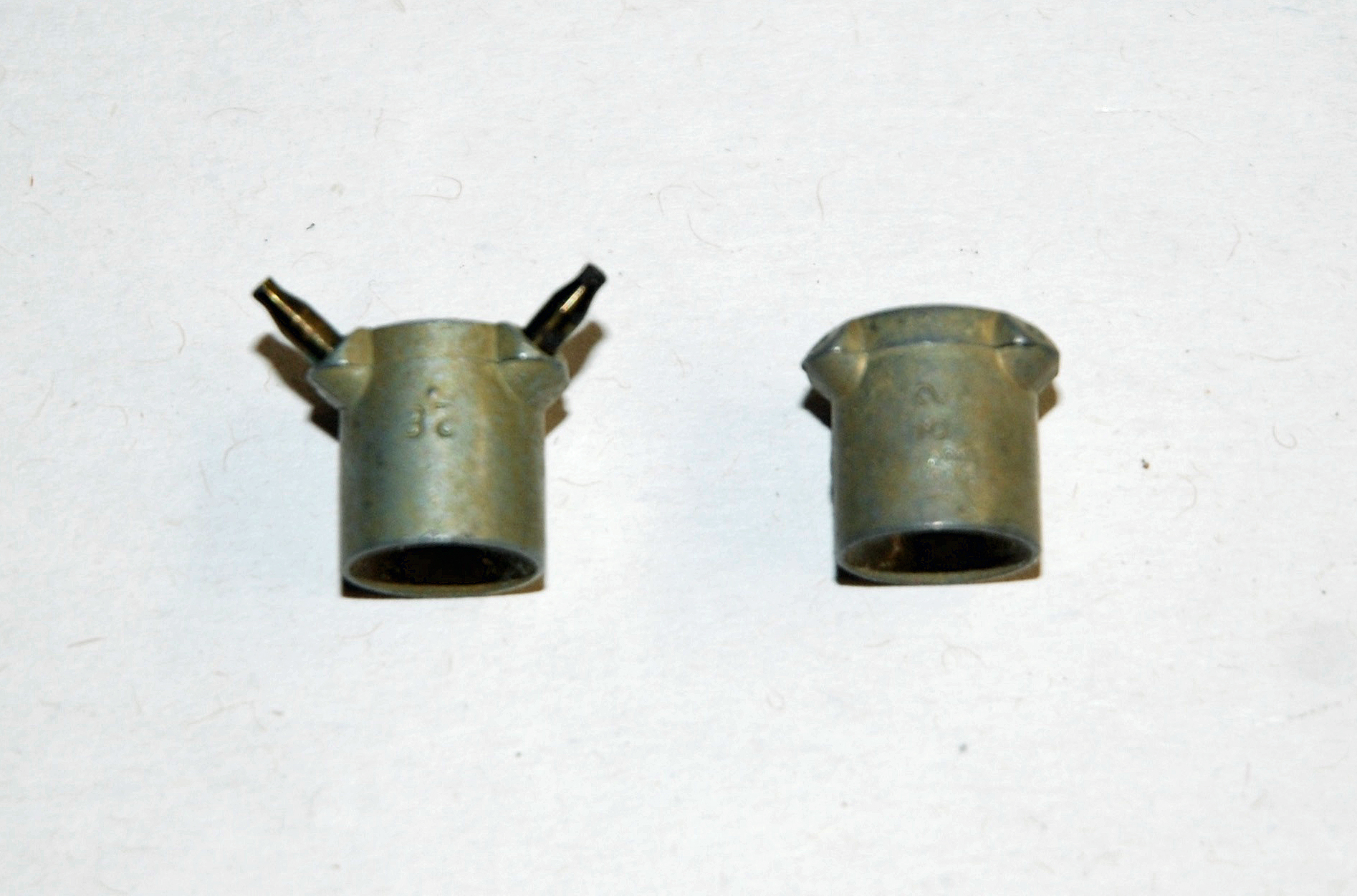
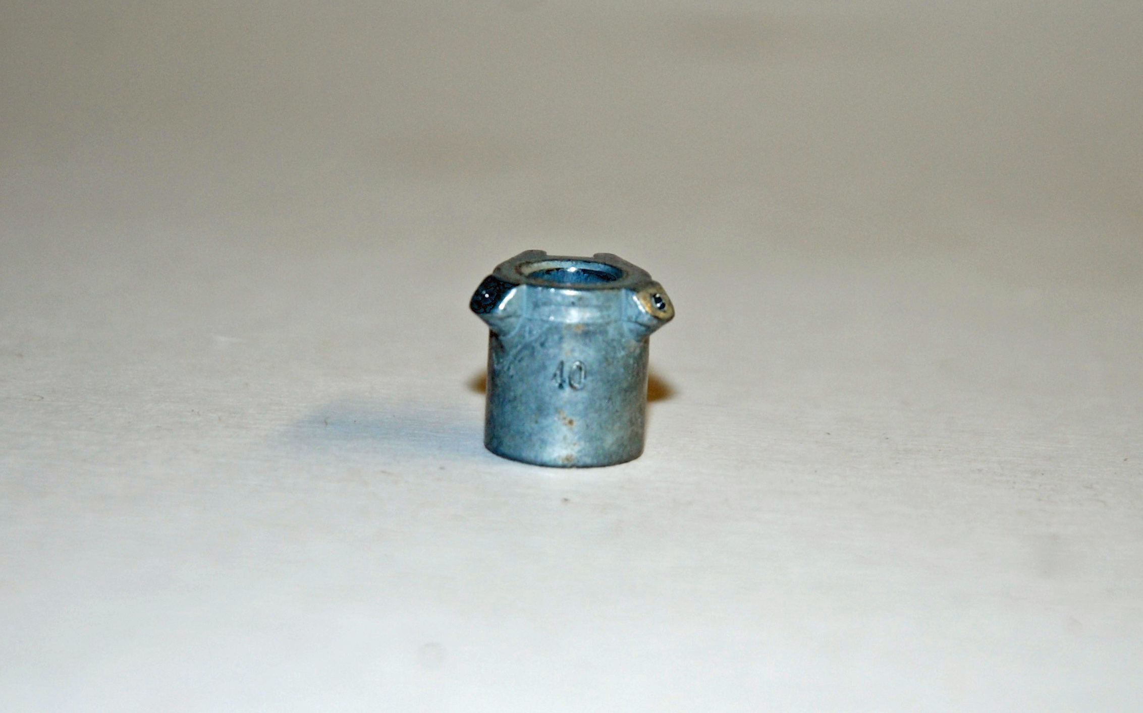
The amount of fuel actually being delivered by one accelerator-pump stroke is determined by the capacity of the pump along with the profile of the accelerator pump cam. While some might think that a larger shooter will deliver more fuel, this is not correct. An accelerator-pump system is either 30 or 50cc, period. The squirter size affects the time that it takes for that fuel to be delivered by controlling the actual flow into the venturi. Holley accelerator pump nozzles are all stamped with a number that coincides with the diameter of the hole size. For example, a #40 shooter will have a hole size that measures 0.040-inch in diameter. Pump shooters or nozzles are available from sizes 25 through to 52. The largest nozzles are only suitable for use with 50 cc accelerator pumps, and well look at those down the page.
A larger squirter allows delivery of the fuel much quicker than a smaller squirter nozzle. If you notice that your car first hesitates and then accelerates, it’s a sure bet that the pump-nozzle size should be increased. If a backfire (lean condition) is experienced when accelerating, this also calls for a larger pump-nozzle size. Conversely, if the car does not feel crisp or clean during off-idle acceleration, the pump-nozzle size may need to be decreased. Heavier cars, relatively mild engine combinations, those with lower numerical axle ratios and those with manual transmissions typically can make use of smaller pump nozzles (for example, shooters numbered 25-30). Lighter cars, cars with automatic transmissions or those with more engine modifications or those with higher numerical axle ratios can make use of larger pump nozzles (for example, shooters numbered 35-40).
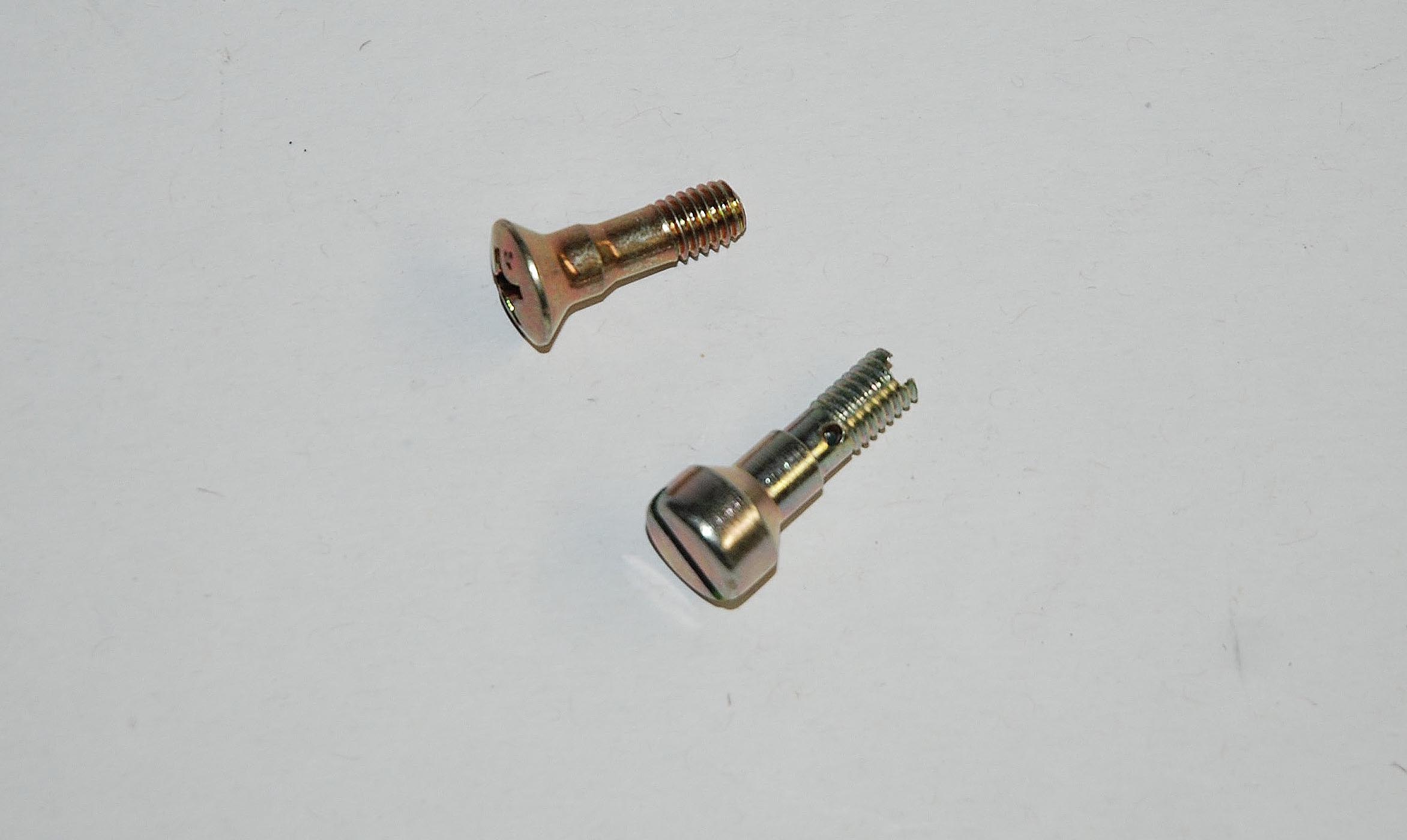
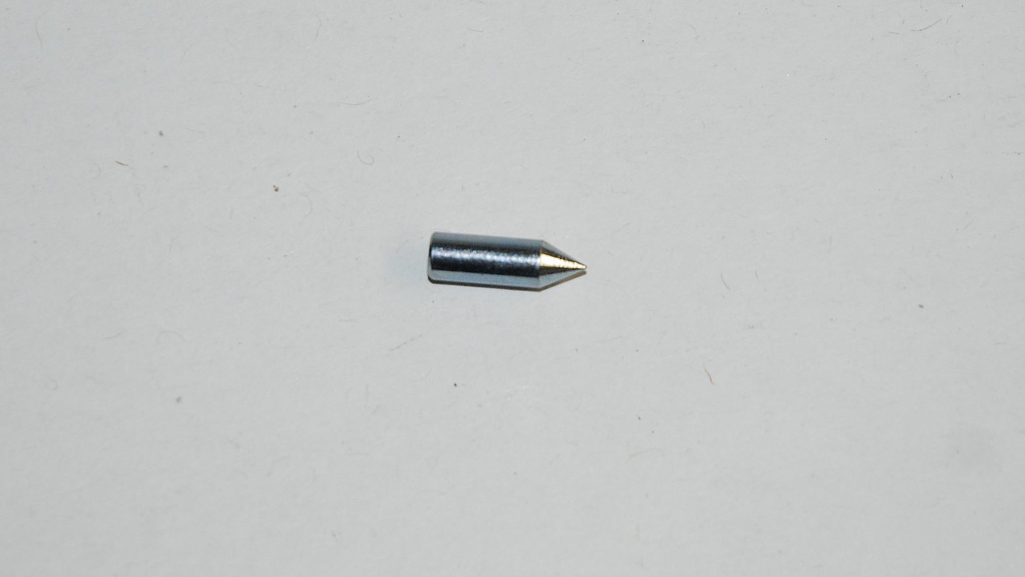
Whenever a #40 or larger accelerator pump nozzle is installed, you should replace the nozzle screw with a hollow example. This screw allows for more fuel flow to the pump nozzle. This ensures that the pump nozzle (not the screw) is the limiting restriction in the system. By the way, you should also be aware of the check valve needle that is underneath each shooter. It can be removed by turning the carburetor upside down (pointed side of the check valve faces down). This is important if you’re adjusting the shooters with the carb off the engine. Holley recommends that when tuning pump nozzles, you move up three sizes at a time: “If there is currently a hesitation with a number 28 pump nozzle, try a number 31 pump nozzle.”
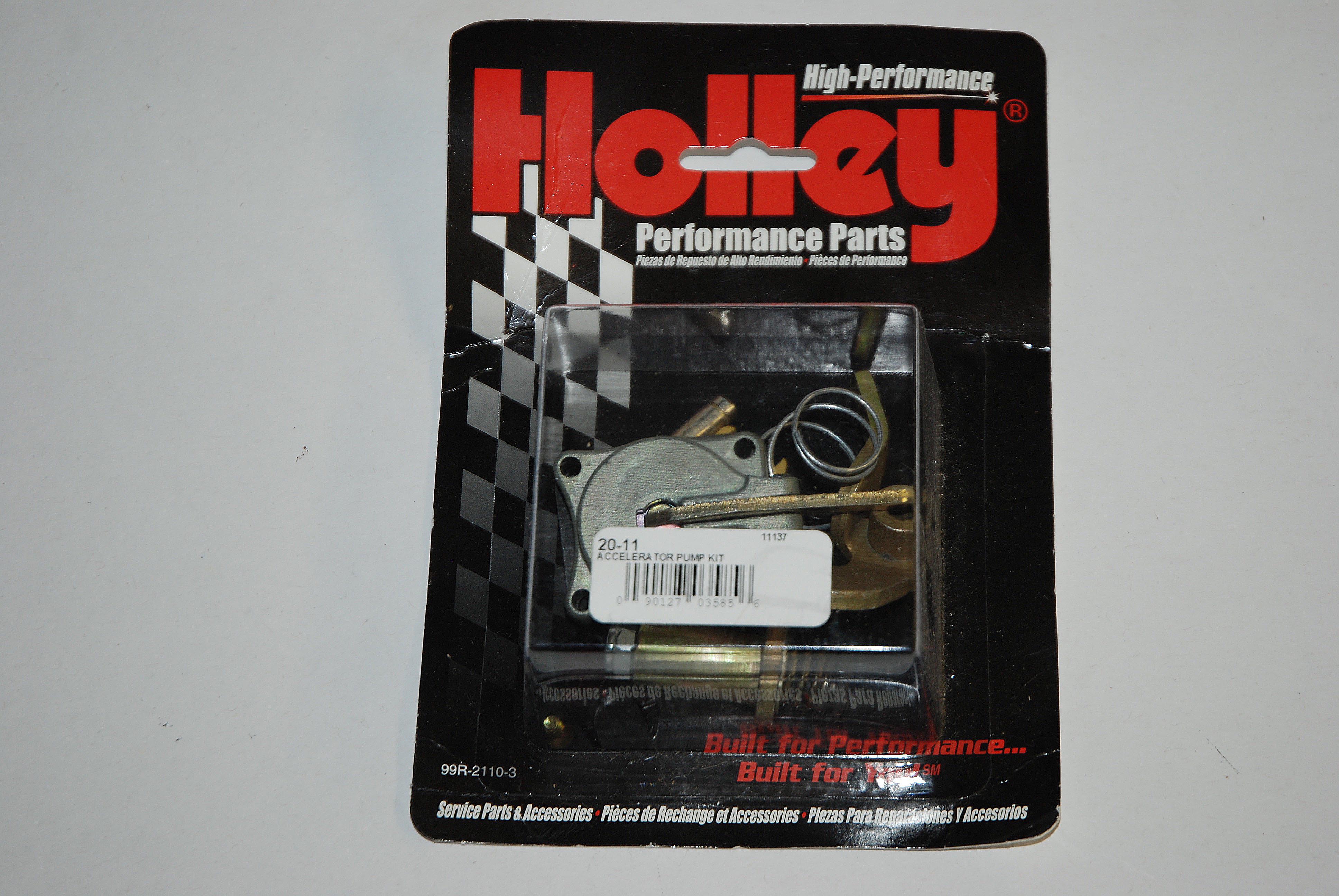
If you find you need a number 37 or larger pump nozzle, then its time to step up to a 50 cc “REO” kit (Holley part number 20-11).
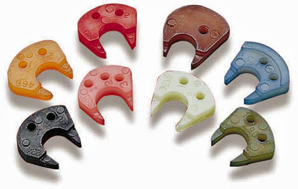
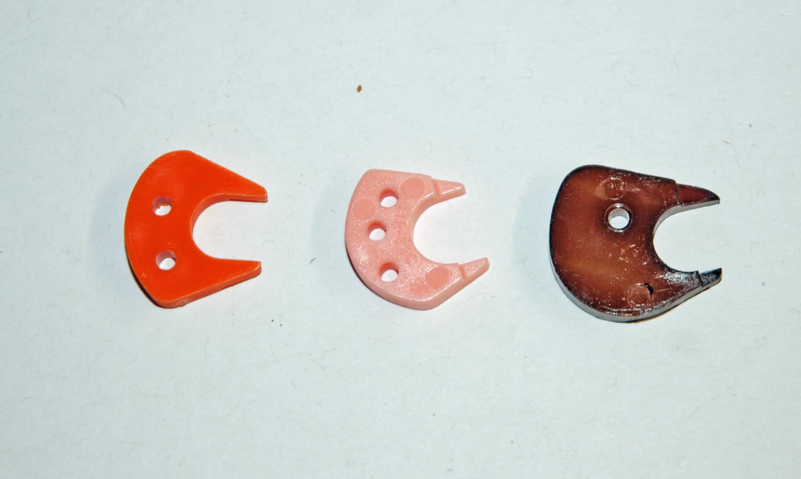
Once the proper squirter size has been selected, the accelerator-pump system can be further tuned by the pump cam. Holley offers an assortment of different pump cams, each with different lift and duration profiles (Holley part number 20-12). The cam profile affects the actual movement of the accelerator-pump lever and consequently, the amount of fuel available at the pump nozzle. Changing a pump cam is done by removing one screw, removing the old cam, and then placing the new pump cam next to the throttle lever, and re-installing the screw. Sometimes, there are two or three numbered holes in each pump cam. When inserting the screw in number one, this activates the accelerator pump early, allowing full use of the pump capacity. In general, most vehicles that typically run at lower idle speeds (600 or 700 rpm) find this position more useful, because they can have a good pump shot available right off this relatively low idle. Screw positions number two or three will delay the pump action. These two cam positions are usually better when used on engines that idle at 1,000 rpm or higher. Pump arm clearance and adjustment should be verified each time the pump cam is replaced or when the pump cam position is changed.
We also need to discuss the actual accelerator pump. Like we said, there are two -- sized 30 and 50cc. The larger accelerator pump is sometimes required on heavily modified engines – particularly those with an automatic transmission. These combinations can experience a flat spot (bog) right after good initial acceleration. It simply means the carburetor ran out of fuel in the accelerator pump circuit and the booster venturi fuel flow wasn’t sufficient to keep the engine running efficiently. In this case, the larger pump capacity will help during the transition. While this is a common modification on automatic-transmission equipped cars, the 50cc is also sometimes a necessity with 2 X 4 tunnel ram applications as well.
By the way for you curious types, the 30 and 50cc capacity is the volume of fuel that is displaced from the accelerator pump in 10 complete strokes of the pump arm. So the actual capacity is 1/10 that number or roughly 3 and 5cc respectively when opening the throttle from idle to wide open. The 50cc pump is easily recognizable by the large pump arm with the encapsulated spring. The 50cc pump also uses a larger pump cam -- either brown (conventional carburetors), or a yellow color (regularly used on 4500-series carburetors).
https://www.racingjunk.com/news/2017/06/19/how-and-why-to-adjust-a-holley-carburetor-accelerator-pump/ Click Here to Begin Slideshow
How many times have you seen or heard a car try to take off when the light goes green, and for some unexplainable reason, it hesitates, or worse, stalls? The reason might not be unexplainable, and nine times out of ten it is caused by a simple adjustment being out of adjustment.
In order to get a stock or mildly modified engine to accelerate smoothly, when you push down on the accelerator pedal, you typically need both an advance in ignition timing and an increase in fuel delivery. In a stock or mildly modified street machine, the distributor vacuum advance senses when you open the throttle and then provides additional timing advance that is required. But it is the duty of the accelerator pump on your carburetor to provide the momentary increase in fuel flow.
The accelerator pump circuit(s) in a Holley carburetor acts to smooth the transition between the idle circuit and the main circuit. When properly adjusted, there will be no hesitation or stumble when the throttle is opened. In operation, the accelerator pump is connected by a linkage to the throttle butterfly shaft. When you accelerate, the accelerator pump squirts a spray of fuel directly into the throttle bores of the carburetor. This overcomes the momentarily lean condition by adding a shot of extra fuel.
Differences in vehicle weight, transmission, and rear axle ratios will affect how much fuel along with the delivery rate of the fuel that must be provided by the accelerator pump. Given these factors, there’s a good chance you’ll have to tune the accelerator pump circuit to fit the needs of your vehicle. A straightforward series of adjustments can sort out the accelerator pump circuit(s) in your Holley carburetor:
On a Holley carburetor, the accelerator pump is located on the bottom of the float bowl. The accelerator-pump system consists of three main components: the pump diaphragm, the pump cam, and the pump nozzle (“squirter” or “shooter”). If your car is experiencing a stumble, begin by first checking the clearance between the pump operating lever (beneath the screw and spring) and the pump diaphragm arm. Do this at wide-open throttle (with the fast idle cam disengaged); the clearance should be approximately 0.015-inch. If there is too much clearance (or conversely, not enough clearance), hold the screw at the bottom and adjust the nut at the top of the spring. Double-check the clearance (with a feeler gauge) at wide-open throttle. If the clearance is correct, you’ll see the pump arm move down as the feeler gauge blade is inserted. When you remove it, you’ll see the arm move back up a bit. The reason for the clearance is to ensure the pump diaphragm is never stretched to the maximum limit at wide-open throttle. Next, you will want to make sure that the accelerator-pump arm starts to move simultaneously with the throttle.
The amount of fuel actually being delivered by one accelerator-pump stroke is determined by the capacity of the pump along with the profile of the accelerator pump cam. While some might think that a larger shooter will deliver more fuel, this is not correct. An accelerator-pump system is either 30 or 50cc, period. The squirter size affects the time that it takes for that fuel to be delivered by controlling the actual flow into the venturi. Holley accelerator pump nozzles are all stamped with a number that coincides with the diameter of the hole size. For example, a #40 shooter will have a hole size that measures 0.040-inch in diameter. Pump shooters or nozzles are available from sizes 25 through to 52. The largest nozzles are only suitable for use with 50 cc accelerator pumps, and well look at those down the page.
A larger squirter allows delivery of the fuel much quicker than a smaller squirter nozzle. If you notice that your car first hesitates and then accelerates, it’s a sure bet that the pump-nozzle size should be increased. If a backfire (lean condition) is experienced when accelerating, this also calls for a larger pump-nozzle size. Conversely, if the car does not feel crisp or clean during off-idle acceleration, the pump-nozzle size may need to be decreased. Heavier cars, relatively mild engine combinations, those with lower numerical axle ratios and those with manual transmissions typically can make use of smaller pump nozzles (for example, shooters numbered 25-30). Lighter cars, cars with automatic transmissions or those with more engine modifications or those with higher numerical axle ratios can make use of larger pump nozzles (for example, shooters numbered 35-40).
Whenever a #40 or larger accelerator pump nozzle is installed, you should replace the nozzle screw with a hollow example. This screw allows for more fuel flow to the pump nozzle. This ensures that the pump nozzle (not the screw) is the limiting restriction in the system. By the way, you should also be aware of the check valve needle that is underneath each shooter. It can be removed by turning the carburetor upside down (pointed side of the check valve faces down). This is important if you’re adjusting the shooters with the carb off the engine. Holley recommends that when tuning pump nozzles, you move up three sizes at a time: “If there is currently a hesitation with a number 28 pump nozzle, try a number 31 pump nozzle.”
If you find you need a number 37 or larger pump nozzle, then its time to step up to a 50 cc “REO” kit (Holley part number 20-11).
Once the proper squirter size has been selected, the accelerator-pump system can be further tuned by the pump cam. Holley offers an assortment of different pump cams, each with different lift and duration profiles (Holley part number 20-12). The cam profile affects the actual movement of the accelerator-pump lever and consequently, the amount of fuel available at the pump nozzle. Changing a pump cam is done by removing one screw, removing the old cam, and then placing the new pump cam next to the throttle lever, and re-installing the screw. Sometimes, there are two or three numbered holes in each pump cam. When inserting the screw in number one, this activates the accelerator pump early, allowing full use of the pump capacity. In general, most vehicles that typically run at lower idle speeds (600 or 700 rpm) find this position more useful, because they can have a good pump shot available right off this relatively low idle. Screw positions number two or three will delay the pump action. These two cam positions are usually better when used on engines that idle at 1,000 rpm or higher. Pump arm clearance and adjustment should be verified each time the pump cam is replaced or when the pump cam position is changed.
We also need to discuss the actual accelerator pump. Like we said, there are two -- sized 30 and 50cc. The larger accelerator pump is sometimes required on heavily modified engines – particularly those with an automatic transmission. These combinations can experience a flat spot (bog) right after good initial acceleration. It simply means the carburetor ran out of fuel in the accelerator pump circuit and the booster venturi fuel flow wasn’t sufficient to keep the engine running efficiently. In this case, the larger pump capacity will help during the transition. While this is a common modification on automatic-transmission equipped cars, the 50cc is also sometimes a necessity with 2 X 4 tunnel ram applications as well.
By the way for you curious types, the 30 and 50cc capacity is the volume of fuel that is displaced from the accelerator pump in 10 complete strokes of the pump arm. So the actual capacity is 1/10 that number or roughly 3 and 5cc respectively when opening the throttle from idle to wide open. The 50cc pump is easily recognizable by the large pump arm with the encapsulated spring. The 50cc pump also uses a larger pump cam -- either brown (conventional carburetors), or a yellow color (regularly used on 4500-series carburetors).
https://www.racingjunk.com/news/2017/06/19/how-and-why-to-adjust-a-holley-carburetor-accelerator-pump/ Click Here to Begin Slideshow
Glad you will be doing the adjusting, thanks for explaining what you will be doing
According to the Holley book and my experience, the pump arm has, inherently, a bit of play. Push down very lightly on the arm until the play is taken up and adjust the spring for .015 clearance at idle. Otherwise the shot begins before the butterflies are open enough and causes a momentary lag in performance.
they could be wrong on the timing as well….my last carburated vehicel….the vacuum advnce was on the manifold side of the carb, so when the throttles opened, timing dropped….on some vehicles the vacuum advance is “ported” and responds as the article suggests
Ported only operates when throttle plate lightly uncovers the vac port in the plate bore. Once plate rises to wot. This port is deactivated due to low manifold vac. Shuts vac advance off.
1) if you don’t have clearance , between the exl. pump and the arm,. the exl pump ,. is not closed off ,! and can draw , ” un metered fuel through the exl pump circuit.
2) no mention of motor vacuum / va fuel level ,. and the atomizers pulling un metered fuel.. through, over the top of that circuit. ether..
3) and nothing about what a, ” power valve does.” , to time, ” full jet “, at a given vacuum level..?
this one trick pony gets a “Failing grade “..!
If you have a vacuum advance distributor and it is hooked to direct, manifold vacuum, NO amount of playing with the carb will get rid of the bog, Find a ‘ported’ source or just disconnect it and plug the hose entering ignition and re-set the initial timing. Now, magically, the bog is GONE. And the damn thing will pass an Emissions Test.
Hydro carbons are drastically reduced. I did it to hundreds of cars during my 25 years as ‘The Emissions Guy’.
“If you have a vacuum advance distributor and it is hooked to direct,
manifold vacuum, NO amount of playing with the carb will get rid of the
bog,” why would you say that is?
The pump adjustment should be at 0 lash with throttle at idle position. The 0.015 spec mentioned is the min clearance between the cam and arm at WOT. this is to avoid bottoming the diaphragm. Pump shot should start immediately as throttle is moved… as per the vac advance… the author is wrong. Vac advance does not and should not add advance at moving to WOT. It shuts off at 0 vacuum high load. It is the mechanical advance that adds the timing needed. Vac advance should only add advance at light load part throttle.