

![[Gallery] Okolona Street Rods Kentuckiana V Foundation Car Show](https://www.racingjunk.com/news/wp-content/uploads/2022/04/IMG_0774-e1650040587750-376x206.jpg)
![[Gallery] Road Rats Car Show](https://www.racingjunk.com/news/wp-content/uploads/2022/05/2A-e1651770667920-376x206.jpg)

Crankshafts Part 4
Click Here to Begin Slideshow
Over the past three issues, we’ve taken a detailed look at high performance crankshafts. We’ve been assisted in this effort by Tom Molnar (Molnar Technologies). Tom is a recognized expert in cranks and we’re fortunate that he has shared his in-depth knowledge right through the series. This time around, we’ll wrap it up with an investigation into balancing. Check it out:
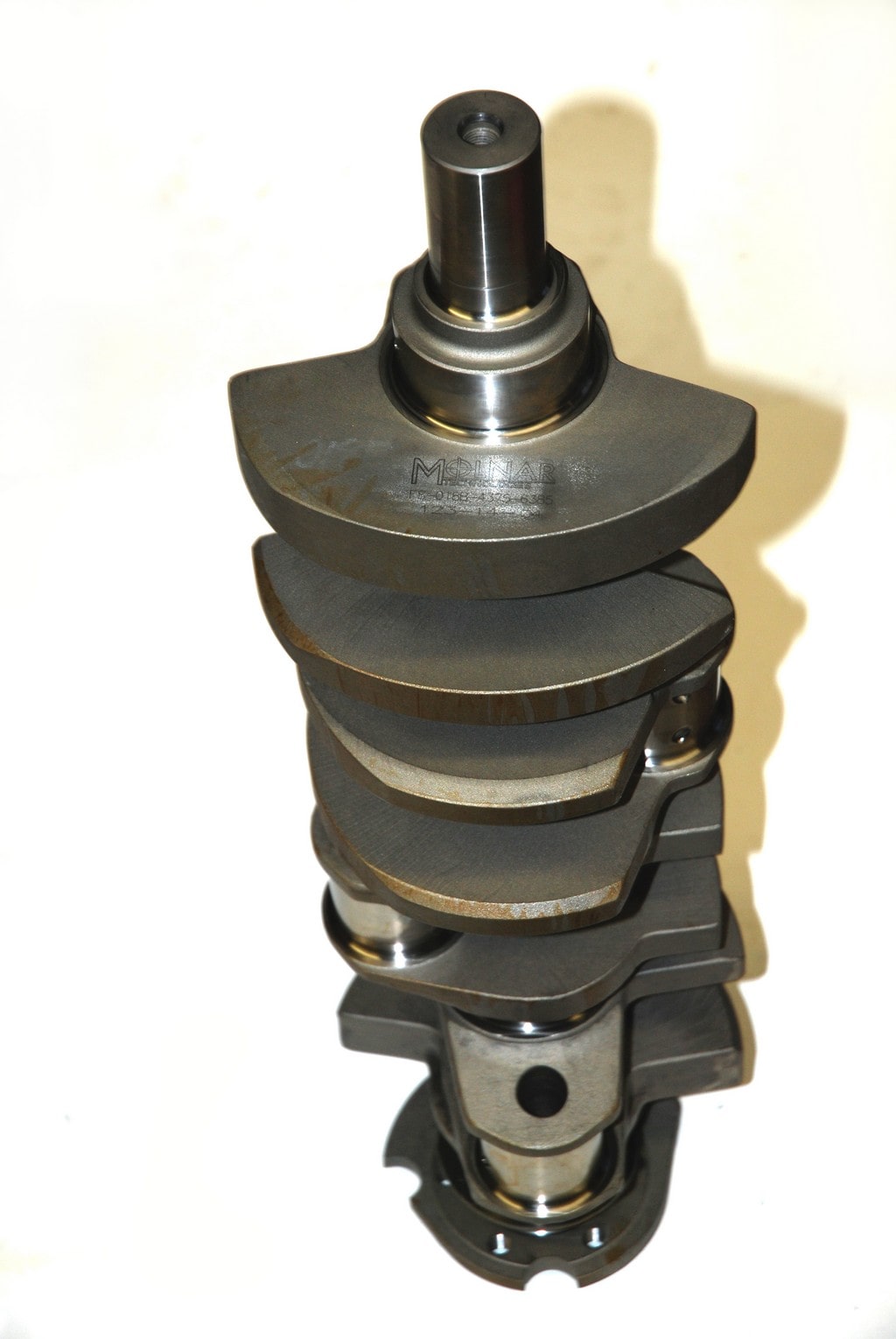
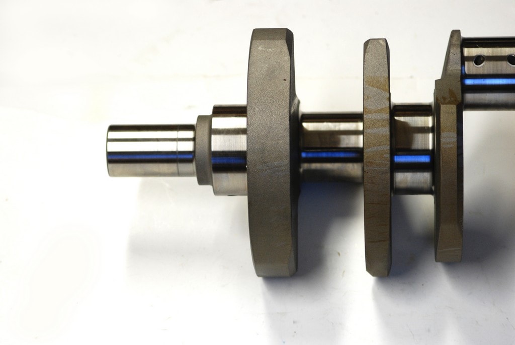
Balancing: If the reciprocating assembly of a given engine isn’t balanced, it will vibrate and ultimately fail, usually prematurely. We touched on this in a previous segment, but we’ll reexamine it: The counterweights of the crankshaft are set in place to offset the rotating (and thrust) forces generated by the combustion process. Inertia plays a role here, and when you spin a crank in a cylinder block it’s easy to see how it works. No secret to most. When you add a heavier piston or a longer stroke or a heavier rod or heavier wrist pin, then a heavier (or larger) counterweight is required. With a common partially counterweighted V8 crank, the engine is split in two (figuratively) – there are counterweights for the front half and counterweights for the back half. Here, the center positions of the crankshaft are left open with no counterweights. As noted previously, that isn’t the case with a fully counterweighted crank. In all cases, when the counterweight is placed further away from the crankshaft centerline, it offers more balance effect. But there’s a catch: Eventually you’ll run out of room in the cylinder block (crank case), and the counterweights will ultimately come in contact with the bottoms of the pistons. Weight placed toward the ends of the crank does have more effect.
Fair enough, but in a production line situation, the original equipment manufacturers generally accept balance tolerances in the range of two ounces. That doesn’t sound like much, but according to CWT, manufacturer of balancing machinery: “2.0 ounce-inch tolerance means that with a typical crankshaft that has a total diameter of 6.0 inches it will have 18.95 grams of unbalance weight residually embedded in the outside edge of the counterweights.
“When the engine is running @ 1000 RPM (just above Idle), the embedded weight will cause the rotating crank assembly to generate a centrifugal unbalance force of 3.56 pounds. As the RPM increases to 2000 the unbalance force increases to 14.25 pounds and at 4000 RPM it is now 56.5 pounds, and 8000 RPM will generate 228 pounds of force.”
Wow! That’s a considerable amount of force thrashing around in your crankcase, threatening to pound out the bearings very quickly. That’s why balancing the reciprocating assembly is so important.
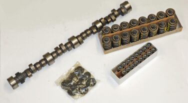
In a high performance engine, the crankshaft must be balanced to the weight of the pistons and connecting rods. Because of this, it’s impossible for the crank manufacturer to balance the crank unless the company has access to all of the reciprocating components. In the balancing process, the large and small ends of the connecting rods, pistons, rings, wrist pins, pin retainers and rod bearings must be weighed. The machinist refers to a chart for the correct weight to add to the crankshaft. The crankshaft is installed in a balancing machine and special clamp-on weights are bolted to the rod journals. These clamp on bob weights are used to simulate the rotating and reciprocating mass of the rods, pistons, rings, pins and associated components.
It’s pretty easy to compare a crankshaft balancer to a dynamic (spin) tire balancer found at tire shops across the nation. Here though, the crank (complete with clamp on weights) is placed on roller bearings and then is wound up to high speed by way of an electric motor. A series of vibration sensors send information to the machine’s electronics. That electronic package determines the amount and location of weight required to correct any imbalance. Typically, the vibration sensors will trigger a strobe light. This in turn freezes the motion of the spinning crankshaft (much like a timing light), indicating where to correctly add or remove weight. Obviously, if the crankshaft counterweights are too heavy, material is removed by way of drilling. If the counterweights are too light, heavy slugs of tungsten metal are added.
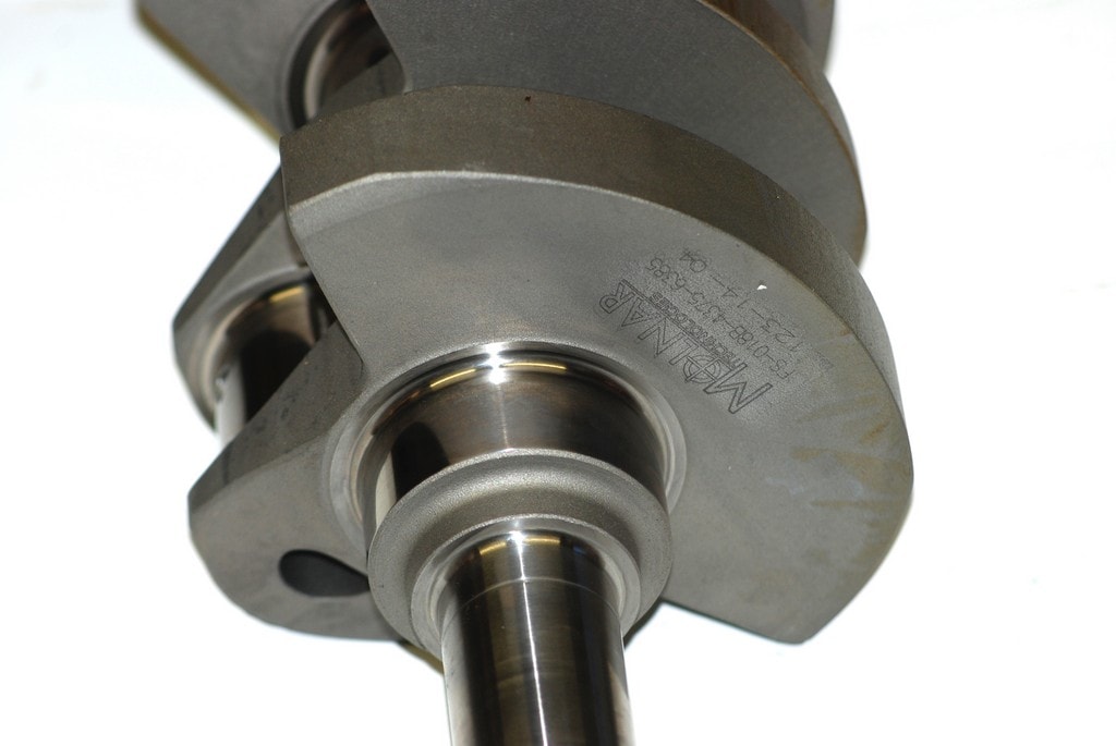
As weight is added, the crankshaft counterweight is drilled in the side, not the end, for the heavy metal slug. What’s the reason for this? If the slug is installed on the end of the crank counterweight, centrifugal force will spit the slug out of the crank (and in turn, right out of the engine). There’s no need to explain the results – they’ll be both spectacular and catastrophic. When a heavy metal slug (typically Tungsten, which is heavier and denser than the steel it replaces) is installed, the machinist refers to a chart depicting the correct slug dimensions (size X diameter) for a given weight. Next, the correct size and depth of hole is drilled into the crank counterweight. A slug of heavy metal is machined to a size (diameter) slight larger than the bored hole in the crank. The slug is then pressed into the hole (interference fit) and ground smooth. At this point, some shops will double check the balance and remove excess weight if necessary.
When all is said and done, the inside story on crankshafts is much more complex than it might first appear. Many thanks to Tom Molnar for providing his insight into the world of cranks! For more, check out the accompanying photos.
Over the past three issues, we’ve taken a detailed look at high performance crankshafts. We’ve been assisted in this effort by Tom Molnar (Molnar Technologies). Tom is a recognized expert in cranks and we’re fortunate that he has shared his in-depth knowledge right through the series. This time around, we’ll wrap it up with an investigation into balancing. Check it out:
Balancing: If the reciprocating assembly of a given engine isn’t balanced, it will vibrate and ultimately fail, usually prematurely. We touched on this in a previous segment, but we’ll reexamine it: The counterweights of the crankshaft are set in place to offset the rotating (and thrust) forces generated by the combustion process. Inertia plays a role here, and when you spin a crank in a cylinder block it’s easy to see how it works. No secret to most. When you add a heavier piston or a longer stroke or a heavier rod or heavier wrist pin, then a heavier (or larger) counterweight is required. With a common partially counterweighted V8 crank, the engine is split in two (figuratively) – there are counterweights for the front half and counterweights for the back half. Here, the center positions of the crankshaft are left open with no counterweights. As noted previously, that isn’t the case with a fully counterweighted crank. In all cases, when the counterweight is placed further away from the crankshaft centerline, it offers more balance effect. But there’s a catch: Eventually you’ll run out of room in the cylinder block (crank case), and the counterweights will ultimately come in contact with the bottoms of the pistons. Weight placed toward the ends of the crank does have more effect.
Fair enough, but in a production line situation, the original equipment manufacturers generally accept balance tolerances in the range of two ounces. That doesn’t sound like much, but according to CWT, manufacturer of balancing machinery: “2.0 ounce-inch tolerance means that with a typical crankshaft that has a total diameter of 6.0 inches it will have 18.95 grams of unbalance weight residually embedded in the outside edge of the counterweights.
“When the engine is running @ 1000 RPM (just above Idle), the embedded weight will cause the rotating crank assembly to generate a centrifugal unbalance force of 3.56 pounds. As the RPM increases to 2000 the unbalance force increases to 14.25 pounds and at 4000 RPM it is now 56.5 pounds, and 8000 RPM will generate 228 pounds of force.”
Wow! That’s a considerable amount of force thrashing around in your crankcase, threatening to pound out the bearings very quickly. That’s why balancing the reciprocating assembly is so important.
In a high performance engine, the crankshaft must be balanced to the weight of the pistons and connecting rods. Because of this, it’s impossible for the crank manufacturer to balance the crank unless the company has access to all of the reciprocating components. In the balancing process, the large and small ends of the connecting rods, pistons, rings, wrist pins, pin retainers and rod bearings must be weighed. The machinist refers to a chart for the correct weight to add to the crankshaft. The crankshaft is installed in a balancing machine and special clamp-on weights are bolted to the rod journals. These clamp on bob weights are used to simulate the rotating and reciprocating mass of the rods, pistons, rings, pins and associated components.
It’s pretty easy to compare a crankshaft balancer to a dynamic (spin) tire balancer found at tire shops across the nation. Here though, the crank (complete with clamp on weights) is placed on roller bearings and then is wound up to high speed by way of an electric motor. A series of vibration sensors send information to the machine’s electronics. That electronic package determines the amount and location of weight required to correct any imbalance. Typically, the vibration sensors will trigger a strobe light. This in turn freezes the motion of the spinning crankshaft (much like a timing light), indicating where to correctly add or remove weight. Obviously, if the crankshaft counterweights are too heavy, material is removed by way of drilling. If the counterweights are too light, heavy slugs of tungsten metal are added.
As weight is added, the crankshaft counterweight is drilled in the side, not the end, for the heavy metal slug. What’s the reason for this? If the slug is installed on the end of the crank counterweight, centrifugal force will spit the slug out of the crank (and in turn, right out of the engine). There’s no need to explain the results – they’ll be both spectacular and catastrophic. When a heavy metal slug (typically Tungsten, which is heavier and denser than the steel it replaces) is installed, the machinist refers to a chart depicting the correct slug dimensions (size X diameter) for a given weight. Next, the correct size and depth of hole is drilled into the crank counterweight. A slug of heavy metal is machined to a size (diameter) slight larger than the bored hole in the crank. The slug is then pressed into the hole (interference fit) and ground smooth. At this point, some shops will double check the balance and remove excess weight if necessary.
When all is said and done, the inside story on crankshafts is much more complex than it might first appear. Many thanks to Tom Molnar for providing his insight into the world of cranks! For more, check out the accompanying photos.
Leave a Reply