

![[Gallery] Okolona Street Rods Kentuckiana V Foundation Car Show](https://www.racingjunk.com/news/wp-content/uploads/2022/04/IMG_0774-e1650040587750-376x206.jpg)
![[Gallery] Road Rats Car Show](https://www.racingjunk.com/news/wp-content/uploads/2022/05/2A-e1651770667920-376x206.jpg)

Crankshafts Part 3
Click Here to Begin Slideshow
In our last issue, we dug deep into what makes up a crank, ending on journals. We’re not quite done with the journal end of the equation, though. We’ll finish our look at them below and then examine polishing, chamfering and cross drilling. Check it out:
When you’re dealing with the main and connecting rod journals of the crank, each must be precise in size and shape to create the proper clearance with the respective bearings. It should be no secret that bearings and crankshaft journals never really touch. The crank operates on a fine layer of oil between the respective surfaces. Trouble can begin when the engine is first started, if it is placed under extreme load or if it experiences even a temporary lack of oil supply. It’s at that point when crankshafts can experience bearing to journal contact. That spells big trouble and usually means you have to regrind the crank.
During the regrind procedure, the crank is mounted in a specialized grinding machine that appears somewhat like a lathe with a large spinning stone wheel. The crank is mounted in the machine; the machinist grinds the main journals and then offsets the chucks in order to grind the rod journals. Grinding a crank isn’t a job for a beginner. It’s a difficult machining operation that mandates both an accomplished machinist and pricey equipment. The machinist must keep a close eye on the stone to keep it dressed. The stone must be straight and the entire operation must be closely monitored with considerable measurements. Crankshafts are reground to standard sizes. That allows you to purchase companion bearings in order to maintain proper oil clearances. These standard regrind sizes are typically 0.001 inch US (Under Size), 0.010 inch US, 0.020 inch US, 0.030 inch US and 0.040 inch US. The regrind operation physically reduces the size of the journals. Not only do they have to be the right size, they also have to be straight, without taper.
Crankshafts are often indexed in race applications. What this means is that the interval between the throws is brought into specification. In a typical V8 fitted with a conventional crankshaft, the rod throws should be exactly 90 degrees apart. For the most part, custom aftermarket cranks are correctly indexed, and the vast majority are “standard” in size (this means they are not ground Under Size).
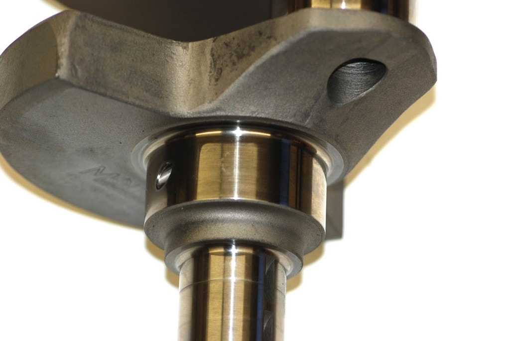
A generous “fillet radius” will be found in a quality high performance or race crankshaft. The fillet radius is the area between the journal and the cheek of the crankshaft. It is also where the crankshaft sees the most stress and it’s also the place where most crankshaft failures take place. More in the photos.
Oil Galleries: Lubricating oil under pressure is delivered to the main bearings as they rotate in the saddle in the block. Oil is forced through drilled passages in the crank to the connecting rod journals. A certain amount of oil is forced (leaks) out of the main and rod journals. It sprays onto the cylinder walls, where it lubricates and cools the pistons and wrist pins as well as the lobes of the camshaft.
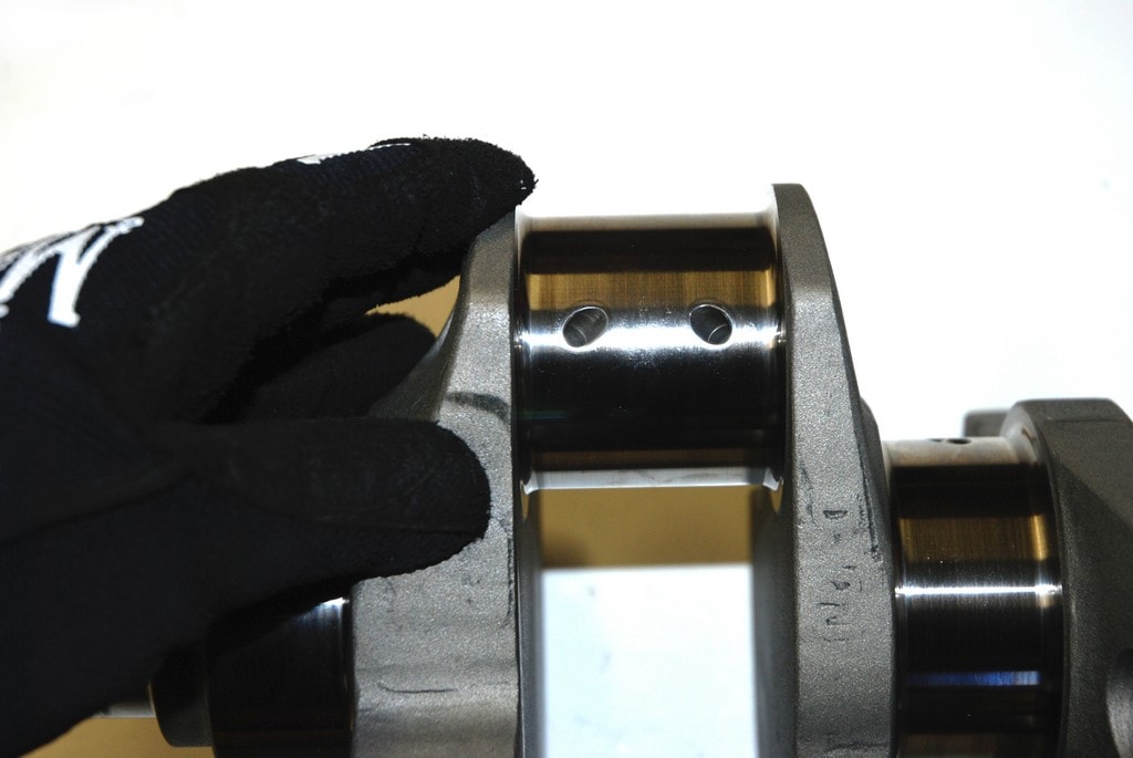
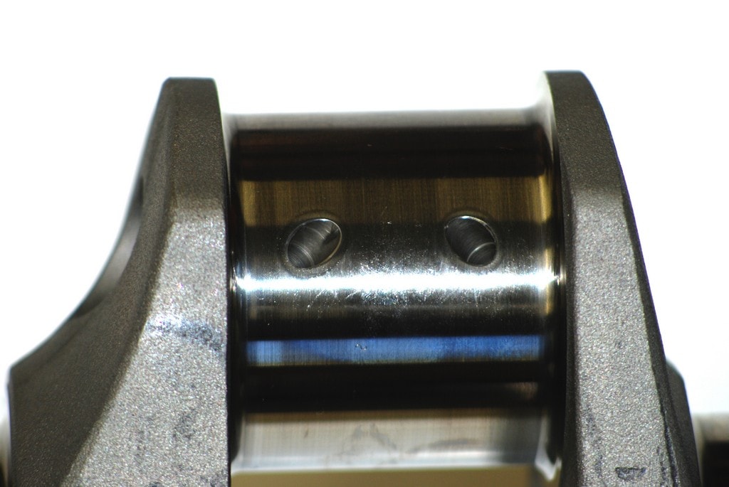
There’s more to oiling: In the sixties, seventies and beyond, it was thought that a simple cross-drilled main journal was an advantage when it came to internal crank oiling. Additional holes were drilled in the main journals, intersecting at right angles. The premise here was that it would help to equalize oil (or even increase) the flow of oil to the bearing by way of a ½-grooved bearing. Factory high performance big block Chevy’s and other engines even came from the factory with cross-drilled crankshafts; however, manufacturers and race engine builders have determined that a cross-drilled crank might not be the best for performance. The cross drilling can actually starve the bearings. At higher engine speed, centrifugal force will actually suck the oil out of the rod bearing holes when the crankshaft is cross-drilled. Not exactly good news. This made for plenty of spun bearings and lots of agony and lots of head scratching. Because of this, you may be better off staying away from a cross drilled crank, at least with the OEM layout.
It’s not that difficult to check a crank to see if it is cross-drilled: Insert a section of straight mechanic’s wire through the main bearing oil holes. If it goes straight through to the other side of the same journal, then the crank is cross-drilled.
Crankshaft Polishing: As a crankshaft is ground, the stones leave a surface finish on the journal that isn’t perfectly smooth. Given this, journals are often ground to a size that very slightly larger than the final size. The journals typically are 0.0005 inch or so over size. The remaining material is then removed from the journals on a crankshaft-polishing machine.
Just like the crank grinding operation mentioned earlier, the polishing job mandates a good amount of skill. Case-in-point is the fact that it’s easy enough to polish a crank right into a slight taper. This can happen when the crank is polished using a back and forth motion. In this case, the polishing job will actually wear the middle of the journal more than the outer edges. The job of polishing leaves a microscopic “nap” of the metal on the surface of the journal. As the crankshaft is polished, the machinist has to ensure that crankshaft turns in the same direction as it spins inside the engine block. If it isn’t done this way, the nap that results from the polishing will eventually wear into the bearing surface.
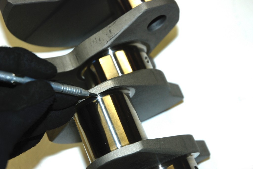
Chamfering: After a crank has been ground or reground, the oil holes in the journals will have sharp edges (some will also have burrs). If the engine is operated as-is, there’s a good chance the bearing will be scored. The solution is to lightly chamfer the oil holes to remove the sharp edge. Not only does this eliminate the chance to score a bearing, it also helps to promote the flow of lubricant. Chamfers are usually accomplished by hand with a die grinder and a tapered stone. Most often, the chamfer is just a small bevel ground at a 45-degree angle. The general idea isn’t to dig a hole in the crankshaft - all you need to do is break the sharp edges.
Internal or External Balancing: Engines can be balanced in two ways -- internally or externally. With an internal balance arrangement, all the required balancing is accomplished on the crankshaft counterweights. The harmonic damper (balancer) and the flywheel are not fitted with extra counterweights. If the engine is balanced externally, a part of the balance weight is on the counterweight while the remainder is affixed to the flywheel and the damper.
Tom Molnar provides notes: “Back to the bending issue, you have forces from the rod pin side of the centerline pulling on the crank in one direction, and the counterweights’ job is to counter these forces to reduce bending. Ideally, the counterweight should be exactly opposite of the forces it is trying to cover. In the case of an external balance, the counterweight forces are actually outside of the engine and not directly opposite of the forces it is trying to cover. This places huge bending forces on the crank, which can cause the crank to crack due to fatigue. Externally balanced cranks are ok to go to the grocery store, but in a high RPM race engine, it’s really not a very good plan.”
With race engines, it is preferred to balance the engine internally. That’s where the use of heavy metal slugs in a crank often comes in play. Something to keep in mind is that you cannot mix and match components (flywheels and flex plates, for example) between internally balanced and externally balanced engines. If they’re mixed, you can expect some remarkable vibrations and most likely some equally remarkable component failures!
We’re out of room for this segment. Next time around, we’ll wrap up our series on racing cranks. There’s still a lot to learn with regard to balancing. And thanks to Tom Molnar for setting us straight on the topic.
In our last issue, we dug deep into what makes up a crank, ending on journals. We’re not quite done with the journal end of the equation, though. We’ll finish our look at them below and then examine polishing, chamfering and cross drilling. Check it out:
When you’re dealing with the main and connecting rod journals of the crank, each must be precise in size and shape to create the proper clearance with the respective bearings. It should be no secret that bearings and crankshaft journals never really touch. The crank operates on a fine layer of oil between the respective surfaces. Trouble can begin when the engine is first started, if it is placed under extreme load or if it experiences even a temporary lack of oil supply. It’s at that point when crankshafts can experience bearing to journal contact. That spells big trouble and usually means you have to regrind the crank.
During the regrind procedure, the crank is mounted in a specialized grinding machine that appears somewhat like a lathe with a large spinning stone wheel. The crank is mounted in the machine; the machinist grinds the main journals and then offsets the chucks in order to grind the rod journals. Grinding a crank isn’t a job for a beginner. It’s a difficult machining operation that mandates both an accomplished machinist and pricey equipment. The machinist must keep a close eye on the stone to keep it dressed. The stone must be straight and the entire operation must be closely monitored with considerable measurements. Crankshafts are reground to standard sizes. That allows you to purchase companion bearings in order to maintain proper oil clearances. These standard regrind sizes are typically 0.001 inch US (Under Size), 0.010 inch US, 0.020 inch US, 0.030 inch US and 0.040 inch US. The regrind operation physically reduces the size of the journals. Not only do they have to be the right size, they also have to be straight, without taper.
Crankshafts are often indexed in race applications. What this means is that the interval between the throws is brought into specification. In a typical V8 fitted with a conventional crankshaft, the rod throws should be exactly 90 degrees apart. For the most part, custom aftermarket cranks are correctly indexed, and the vast majority are “standard” in size (this means they are not ground Under Size).
A generous “fillet radius” will be found in a quality high performance or race crankshaft. The fillet radius is the area between the journal and the cheek of the crankshaft. It is also where the crankshaft sees the most stress and it’s also the place where most crankshaft failures take place. More in the photos.
Oil Galleries: Lubricating oil under pressure is delivered to the main bearings as they rotate in the saddle in the block. Oil is forced through drilled passages in the crank to the connecting rod journals. A certain amount of oil is forced (leaks) out of the main and rod journals. It sprays onto the cylinder walls, where it lubricates and cools the pistons and wrist pins as well as the lobes of the camshaft.
There’s more to oiling: In the sixties, seventies and beyond, it was thought that a simple cross-drilled main journal was an advantage when it came to internal crank oiling. Additional holes were drilled in the main journals, intersecting at right angles. The premise here was that it would help to equalize oil (or even increase) the flow of oil to the bearing by way of a ½-grooved bearing. Factory high performance big block Chevy’s and other engines even came from the factory with cross-drilled crankshafts; however, manufacturers and race engine builders have determined that a cross-drilled crank might not be the best for performance. The cross drilling can actually starve the bearings. At higher engine speed, centrifugal force will actually suck the oil out of the rod bearing holes when the crankshaft is cross-drilled. Not exactly good news. This made for plenty of spun bearings and lots of agony and lots of head scratching. Because of this, you may be better off staying away from a cross drilled crank, at least with the OEM layout.
It’s not that difficult to check a crank to see if it is cross-drilled: Insert a section of straight mechanic’s wire through the main bearing oil holes. If it goes straight through to the other side of the same journal, then the crank is cross-drilled.
Crankshaft Polishing: As a crankshaft is ground, the stones leave a surface finish on the journal that isn’t perfectly smooth. Given this, journals are often ground to a size that very slightly larger than the final size. The journals typically are 0.0005 inch or so over size. The remaining material is then removed from the journals on a crankshaft-polishing machine.
Just like the crank grinding operation mentioned earlier, the polishing job mandates a good amount of skill. Case-in-point is the fact that it’s easy enough to polish a crank right into a slight taper. This can happen when the crank is polished using a back and forth motion. In this case, the polishing job will actually wear the middle of the journal more than the outer edges. The job of polishing leaves a microscopic “nap” of the metal on the surface of the journal. As the crankshaft is polished, the machinist has to ensure that crankshaft turns in the same direction as it spins inside the engine block. If it isn’t done this way, the nap that results from the polishing will eventually wear into the bearing surface.
Chamfering: After a crank has been ground or reground, the oil holes in the journals will have sharp edges (some will also have burrs). If the engine is operated as-is, there’s a good chance the bearing will be scored. The solution is to lightly chamfer the oil holes to remove the sharp edge. Not only does this eliminate the chance to score a bearing, it also helps to promote the flow of lubricant. Chamfers are usually accomplished by hand with a die grinder and a tapered stone. Most often, the chamfer is just a small bevel ground at a 45-degree angle. The general idea isn’t to dig a hole in the crankshaft - all you need to do is break the sharp edges.
Internal or External Balancing: Engines can be balanced in two ways -- internally or externally. With an internal balance arrangement, all the required balancing is accomplished on the crankshaft counterweights. The harmonic damper (balancer) and the flywheel are not fitted with extra counterweights. If the engine is balanced externally, a part of the balance weight is on the counterweight while the remainder is affixed to the flywheel and the damper.
Tom Molnar provides notes: “Back to the bending issue, you have forces from the rod pin side of the centerline pulling on the crank in one direction, and the counterweights’ job is to counter these forces to reduce bending. Ideally, the counterweight should be exactly opposite of the forces it is trying to cover. In the case of an external balance, the counterweight forces are actually outside of the engine and not directly opposite of the forces it is trying to cover. This places huge bending forces on the crank, which can cause the crank to crack due to fatigue. Externally balanced cranks are ok to go to the grocery store, but in a high RPM race engine, it’s really not a very good plan.”
With race engines, it is preferred to balance the engine internally. That’s where the use of heavy metal slugs in a crank often comes in play. Something to keep in mind is that you cannot mix and match components (flywheels and flex plates, for example) between internally balanced and externally balanced engines. If they’re mixed, you can expect some remarkable vibrations and most likely some equally remarkable component failures!
We’re out of room for this segment. Next time around, we’ll wrap up our series on racing cranks. There’s still a lot to learn with regard to balancing. And thanks to Tom Molnar for setting us straight on the topic.
Leave a Reply