

![[Gallery] Show us Your Mustang! Celebrating 60 Years of Mustang](https://www.racingjunk.com/news/wp-content/uploads/2024/04/Al-Liebmann-376x206.webp)
![[Gallery] Okolona Street Rods Kentuckiana V Foundation Car Show](https://www.racingjunk.com/news/wp-content/uploads/2022/04/IMG_0774-e1650040587750-376x206.jpg)
![[Gallery] Road Rats Car Show](https://www.racingjunk.com/news/wp-content/uploads/2022/05/2A-e1651770667920-376x206.jpg)
Piston Primer Part 3
Click Here to Begin Slideshow
Over the past few issues, we’ve taken a hard look at pistons for street and strip applications. To refresh your memory, we examined the differences between forgings and castings, went over alloys and expansion rates, investigated skirt configurations and scrutinized ring lands along with piston ring clearances in the ring grooves. This time around, we'll dig into deck surfaces, domes, valve reliefs and compression height. Keep in mind - there's a lot more to pistons than first meets the eye.
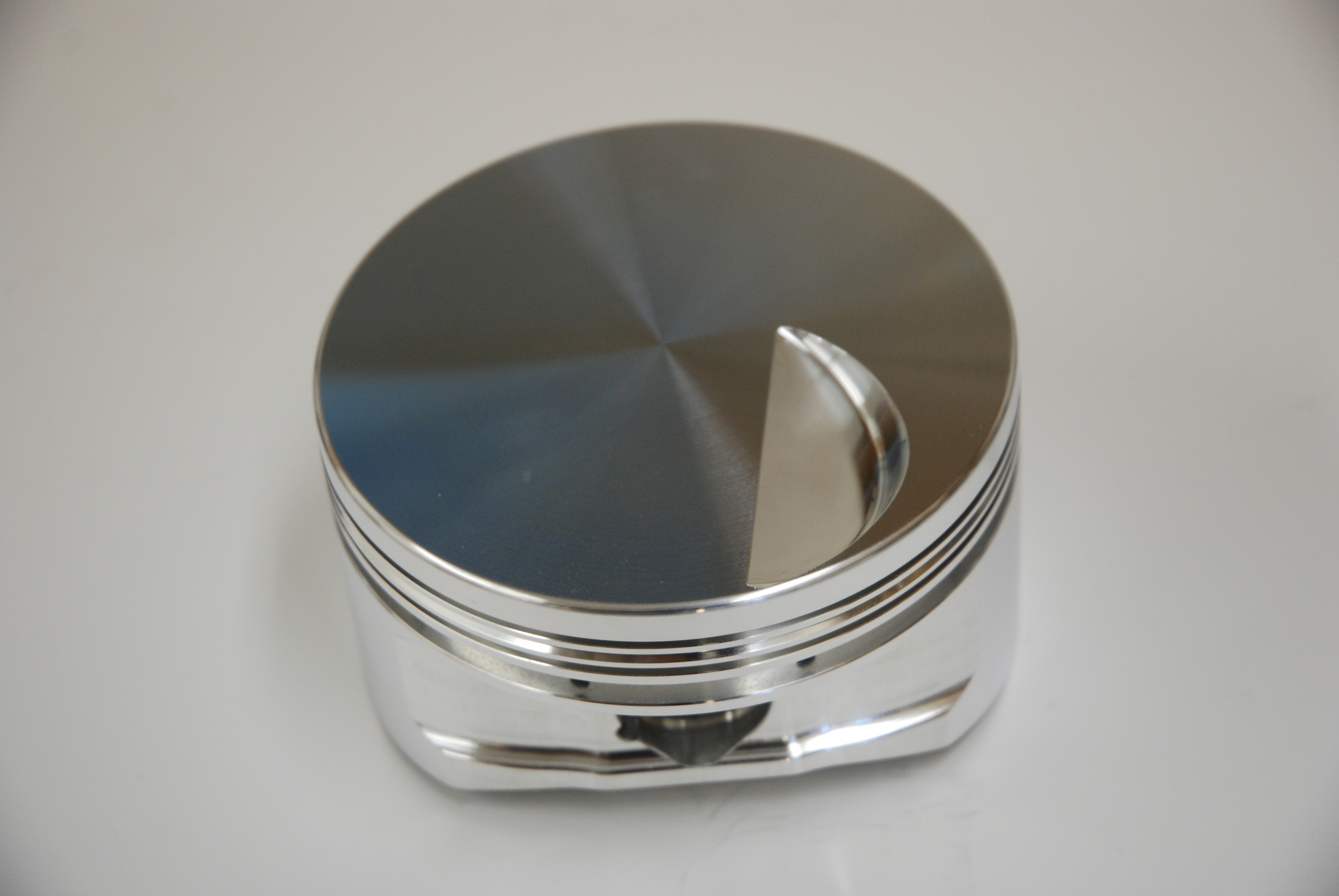
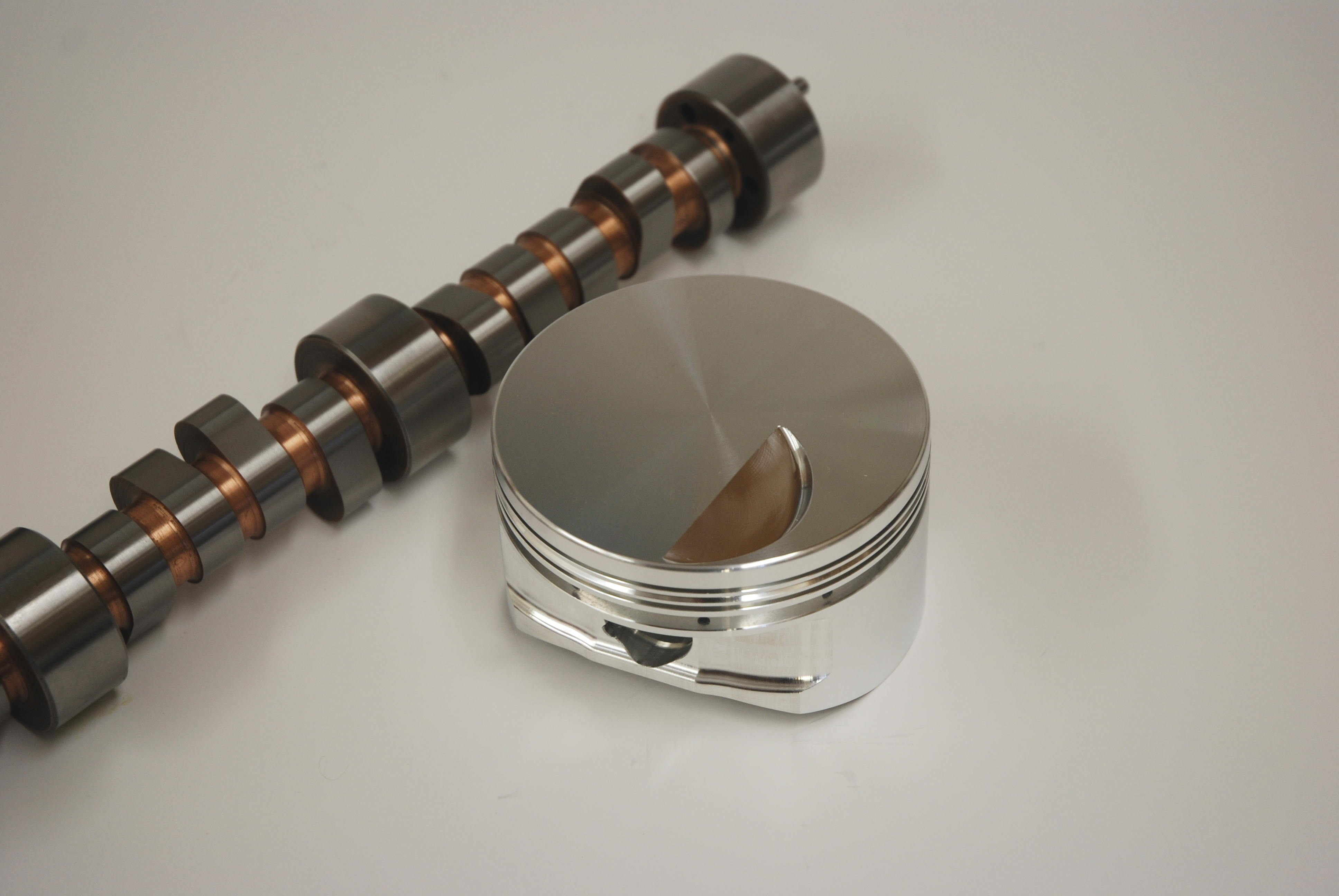
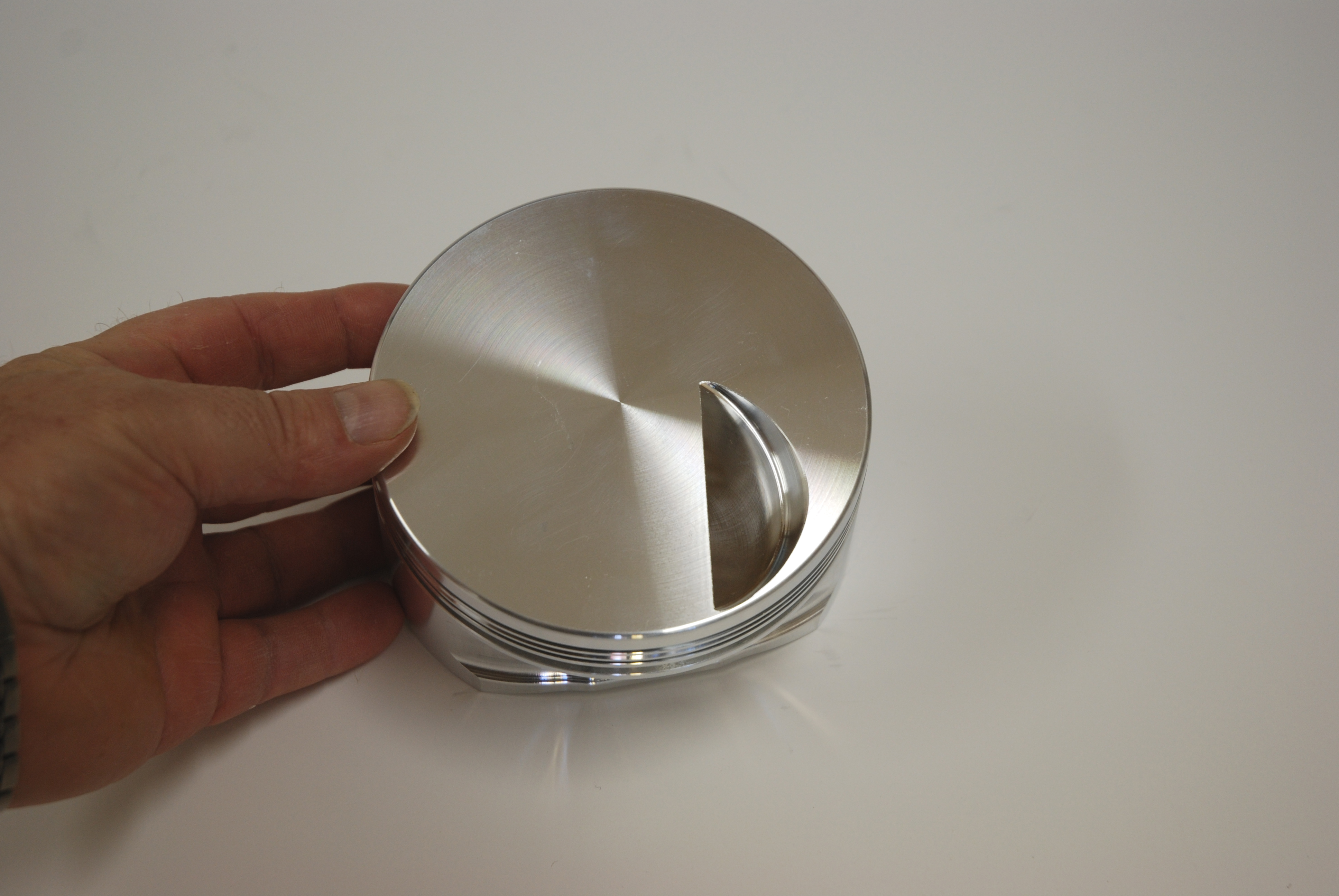
PISTON DOMES - How big a dome can one get away with? Bigger doesn't necessarily mean better. When it comes to piston domes, there is one thing to remember: Any time the dome size is increased, the time it takes for the flame (from the combustion process) to travel will increase. Any time the flame travel duration increases, the quality of the flame will lessen. If at all possible, it's almost always better to increase compression by reducing the size of the combustion chamber rather than by stuffing the chamber with a large dome. Generally speaking, the best piston surface is a flat top without any dome. Heat absorbed by the piston is reduced and flame propagation is improved.
Flat top pistons can't always be used, especially with the cylinder head configurations available today. Because of this, a compromise is the only solution when "big" compression ratios are required. To fill the chamber, most experts agree that a wide, low dome which includes a healthy top radius should be used. Sharp corners or ridges must be eliminated.
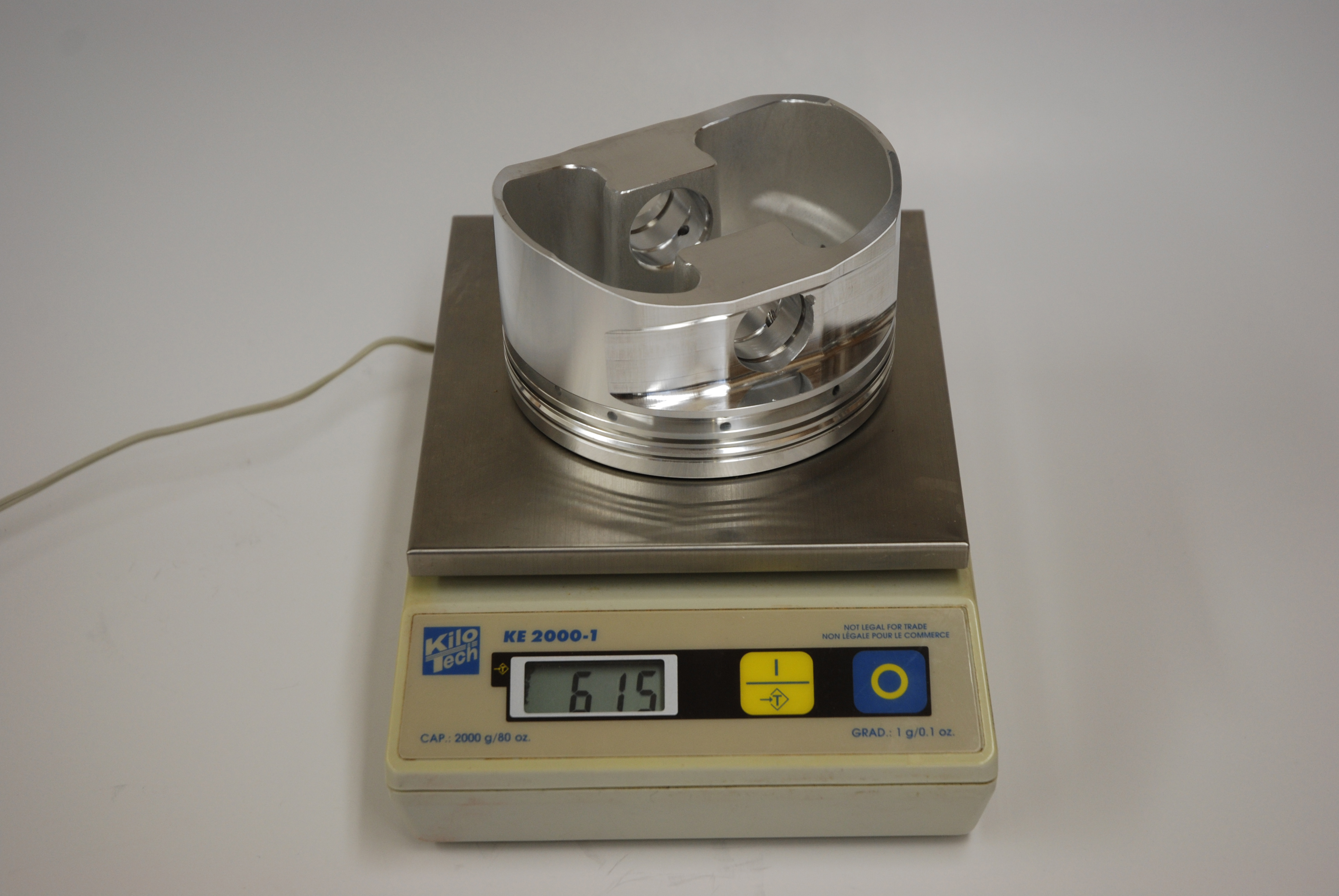
How important is the thickness of the dome and deck surface? The weight of the piston and the thickness of the dome (and deck) are directly related. They're both critical. If a piston dome or deck is too thin, the piston (and engine) can quickly be destroyed by detonation. On the flip side, the best place to remove weight in a piston is under the dome and deck area. How thin can you go? It depends on the combination. As an example, some drag race pistons can survive with as little as 0.080-0.100-inch thick deck surfaces (particularly those used in high RPM small displacement power plants). In comparison, a stock piston for something like a small block Chevy might have a deck-dome thickness of between 0.300-0.400-inch. But a piston with 0.080-inch decks could never survive for any length of time (say, ten or fifteen minutes of operating time). In most cases, it's safe to operate a piston with a deck-dome thickness of between 0.150-0.200-inch (0.0200-inch preferred). One point to consider is the fact that a smaller bore engine can probably get away with a thinner piston deck/dome surface that a large bore example.
Believe it or not, the actual alloy of the piston has an effect upon the thickness of the deck and dome surfaces. Some alloys are better suited for heat dissipation. In addition, anything that can be done to cool the backside of the piston deck and dome surface will improve the life of the piston. This cooling can be accomplished with added oil sprayed under the piston (this might not be such a grand idea when you think about windage losses) or with thermal coatings on the combustion surface.
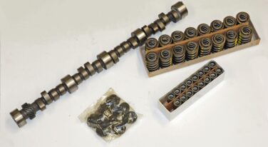
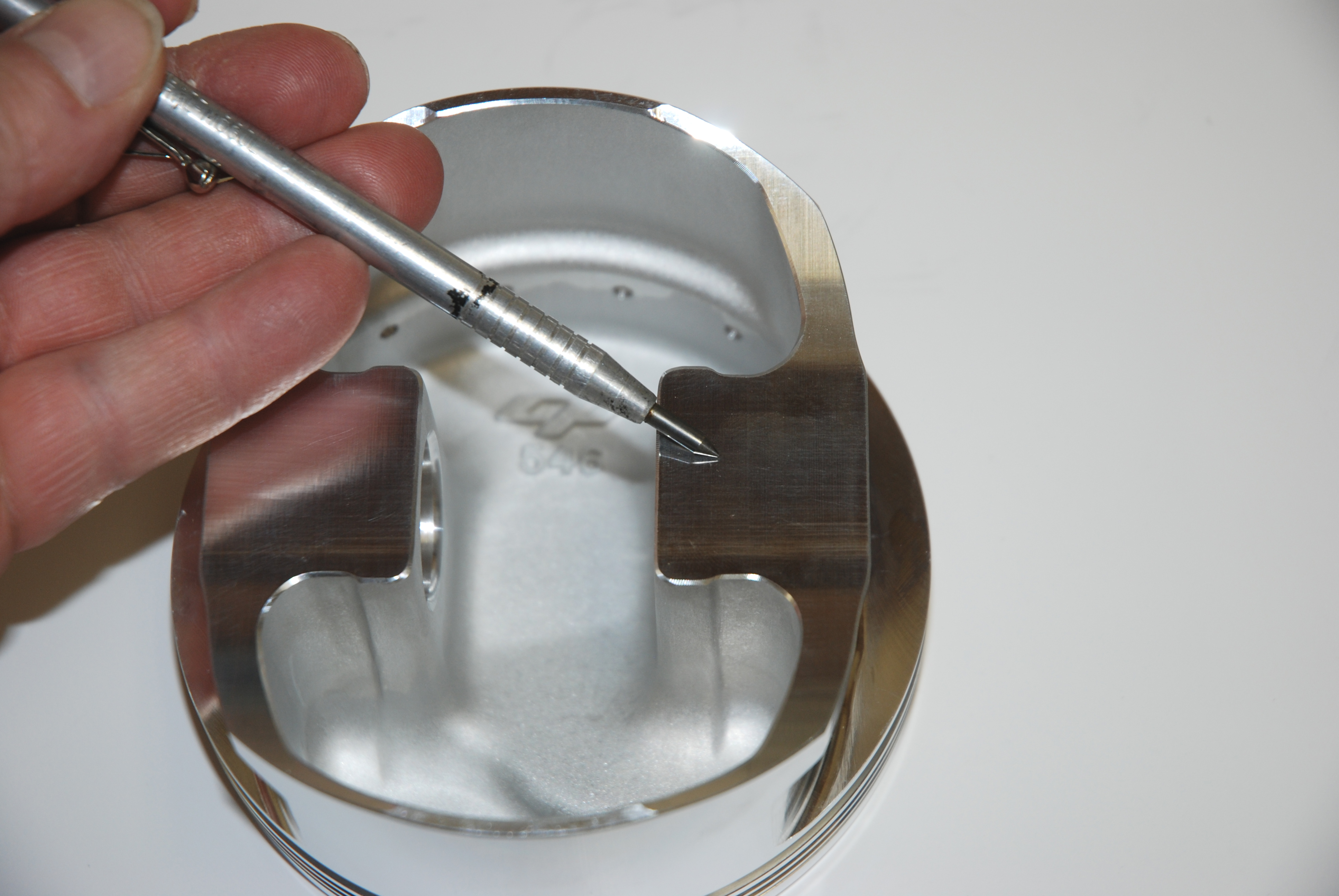
VALVE RELIEFS - Valve reliefs are a necessary evil in any poppet valve power plant. Typically, to increase horsepower, we increase the valve lift and increase the camshaft duration. When the valve lift increases and/or when the duration is increased, then the valve relief depth has to increase. Once you factor in the required valve-to-piston clearance numbers, you can often end up with a good-sized "cavity" on the topside of the piston.
There's more here too: Plenty of stock pistons are built with "universal" construction (good examples include over-the-counter parts store replacement pistons for small block Chevys). This universality means that the pistons can be used on either bank of the engine in any cylinder. Because of that, they have four valve reliefs. In addition, these reliefs are often deep enough for many different cam designs and many different overall valve head diameters. Most pistons designed for racing don't have (or need) this entirely. This yields more compression, simply because the extra (and unnecessary) valve reliefs are eliminated and feature correctly sized (and placed) valve reliefs.
How much piston-to-valve clearance do you need in your engine? In an over-the-counter piston, the figure often works out to 0.150-inch or more, but the actual number you use depends upon the combination. As an example, engines with steel rods can use a tighter piston-to-valve clearance dimension simply because the steel rod doesn't "grow" like an aluminum rod. Some racers have gotten away with figures as small as 0.030-inch (wow!), but that's really living on the edge. One very tiny mistake (like a bit too much RPM on a gear change or a missed shift) can mean a basket full of bent valves. More realistic clearance figures are a minimum of 0.070-inch on the intake side and 0.120-inch on the exhaust side. Another thing to remember when talking about clearances is the "radial clearance" next to the valve. Not only does the valve have to miss the bottom of the valve relief, it also has to clear the sides of the relief. This topic is seldom discussed, but for the most part, a radial clearance of 0.060-inch around both the intake and exhaust valves is important.
Keep in mind too that the deck can be severely weakened if you have to sink the pocket into an already lightened piston. In many combinations, the outside edge of the intake valve relief is the most critical. It is closest to the compression ring (especially if the rings have been moved upward), and by design, the intake valve mandates a bigger pocket since it is more substantial than the exhaust valve.
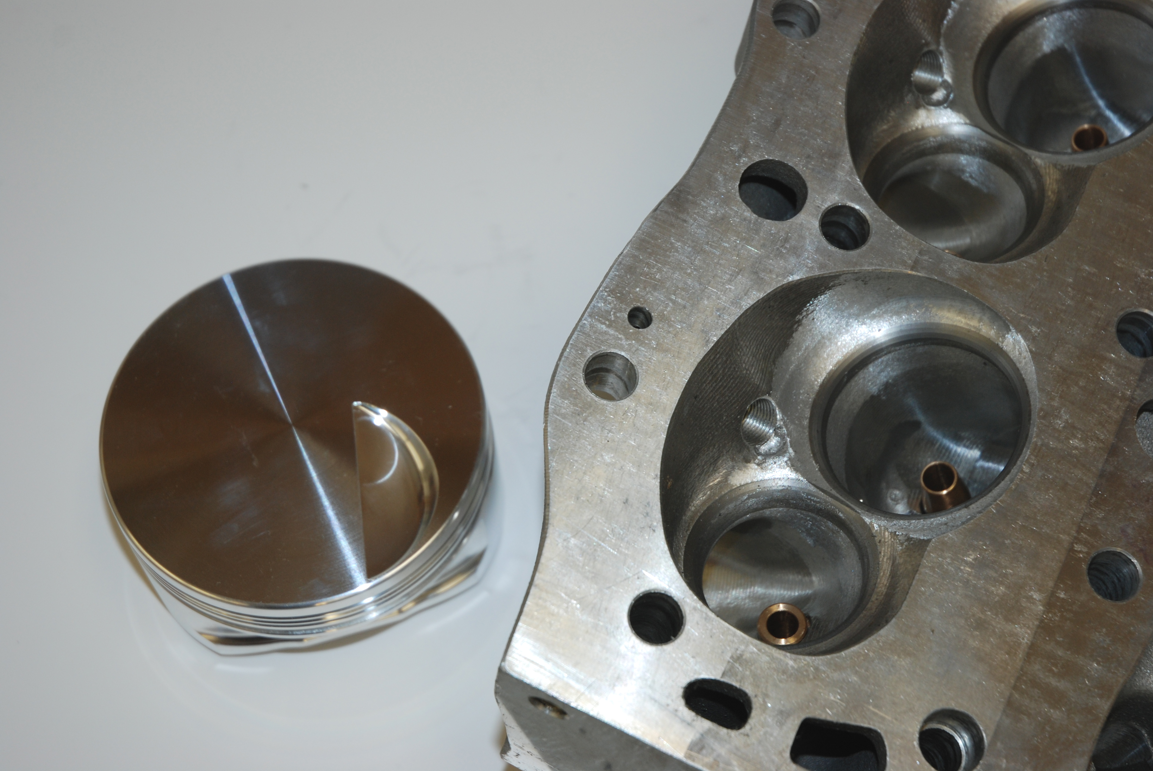
QUENCH & DECK CLEARANCE – The quench area is where the flat part of the combustion chamber meets the flat part of the piston. When the engine is running, the piston and head come together. When this happens during the compression-to-power section of the cycle, combustion gasses are forced into the open areas of the chamber. This makes for more turbulence and better combustion.
Here's where it gets tricky: In order for the quench to operate at its peak, the clearance between the cylinder head deck and the piston deck surface should be as close as possible. The bottom line is pretty basic: The closer the quench figure, the greater the compression ratio and the greater the turbulence (and horsepower). So how close can you come? Before we begin, remember that the compressed gasket thickness enters this equation, as does the overall deck height of the engine. Aluminum rods and engine RPM also influence the quench clearance figure. When all of the smoke, dust and combustion gasses settle, there is no ideal deck clearance, but numbers that approach 0.060-inch (including the compressed gasket thickness) are probably just right for aluminum rods and too large for steel rod engines. Look for a clearance figure of 0.035-0.045-inch for steel rod combinations, but remember that these are not absolute numbers! Generally speaking, the idea is to have the deck clearance as close to zero as possible while the engine is operating at the proper temperature and RPM range. If it's too close, the piston can smack the cylinder head and pinch the top ring land. In the end, this gets expensive. Quickly.
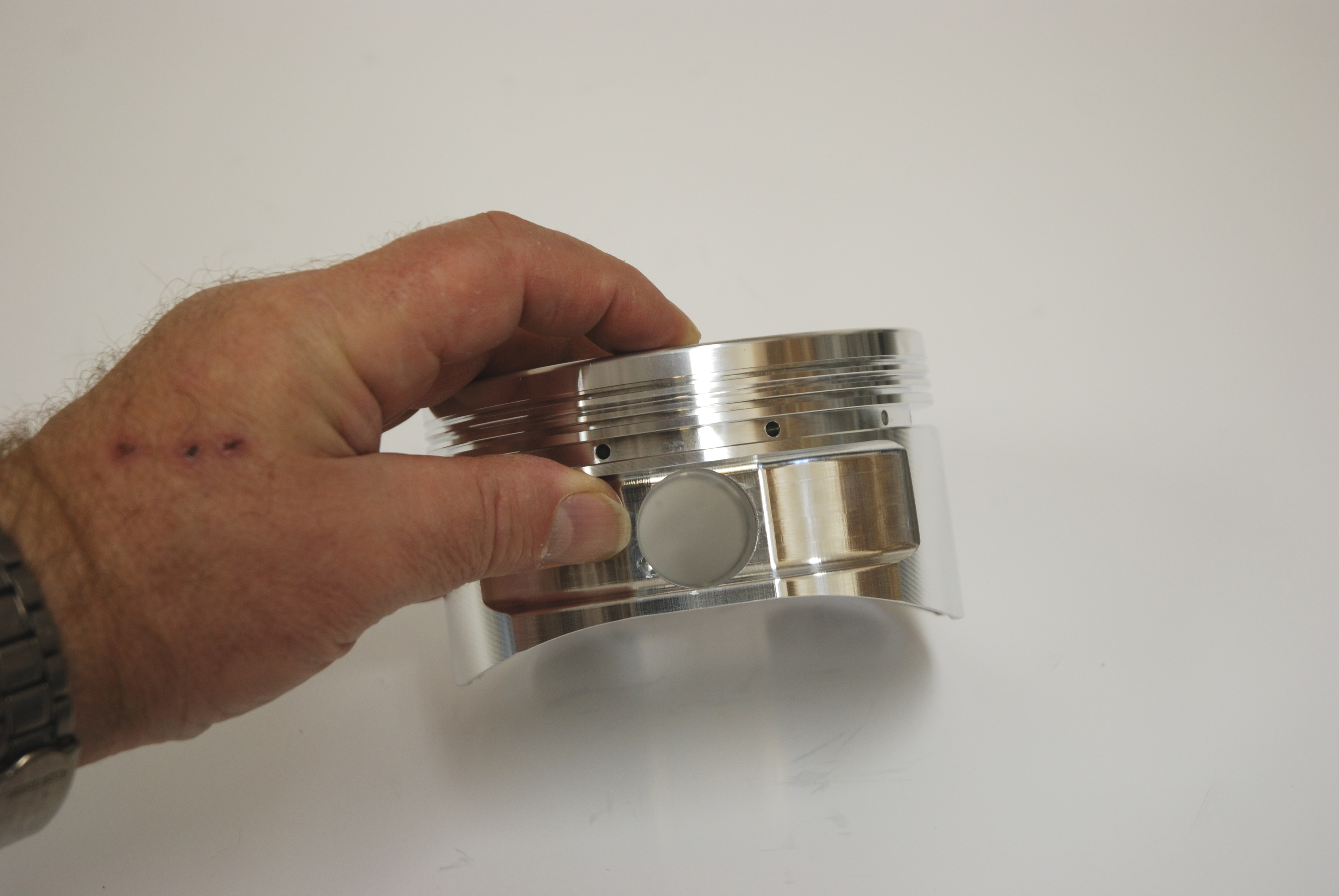
COMPRESSION HEIGHT - Compression height is the distance between the centerline of the wrist pin bore to the top of the piston deck (or quench or "flat"). You can easily run into a problem with compression height when the crankshaft stroke and the connecting rods are long. In something like a small stock-block Chevy application with these characteristics, you simply run out of room.
Let’s assume you've decided to stroke your engine and/or run long rods. In applications such as this, the wrist pin bore can soon creep into the area of the piston reserved for the oil ring. When this happens, many piston manufacturers will incorporate a "support rail" at the bottom of the oil ring. In practice, the piston is assembled onto the connecting rod. The pin and pin locks are installed, then the support rail goes into place. It acts as a bridge over the area where the pin passes through the oil ring groove. The oil ring then installs over this "bridge" and into the groove as normal. This system allows the pin to be moved upward by as much as 0.1875-inch more than normal.
Stop back next week for the final installment of Piston Primer!
Over the past few issues, we’ve taken a hard look at pistons for street and strip applications. To refresh your memory, we examined the differences between forgings and castings, went over alloys and expansion rates, investigated skirt configurations and scrutinized ring lands along with piston ring clearances in the ring grooves. This time around, we'll dig into deck surfaces, domes, valve reliefs and compression height. Keep in mind - there's a lot more to pistons than first meets the eye.
PISTON DOMES - How big a dome can one get away with? Bigger doesn't necessarily mean better. When it comes to piston domes, there is one thing to remember: Any time the dome size is increased, the time it takes for the flame (from the combustion process) to travel will increase. Any time the flame travel duration increases, the quality of the flame will lessen. If at all possible, it's almost always better to increase compression by reducing the size of the combustion chamber rather than by stuffing the chamber with a large dome. Generally speaking, the best piston surface is a flat top without any dome. Heat absorbed by the piston is reduced and flame propagation is improved.
Flat top pistons can't always be used, especially with the cylinder head configurations available today. Because of this, a compromise is the only solution when "big" compression ratios are required. To fill the chamber, most experts agree that a wide, low dome which includes a healthy top radius should be used. Sharp corners or ridges must be eliminated.
How important is the thickness of the dome and deck surface? The weight of the piston and the thickness of the dome (and deck) are directly related. They're both critical. If a piston dome or deck is too thin, the piston (and engine) can quickly be destroyed by detonation. On the flip side, the best place to remove weight in a piston is under the dome and deck area. How thin can you go? It depends on the combination. As an example, some drag race pistons can survive with as little as 0.080-0.100-inch thick deck surfaces (particularly those used in high RPM small displacement power plants). In comparison, a stock piston for something like a small block Chevy might have a deck-dome thickness of between 0.300-0.400-inch. But a piston with 0.080-inch decks could never survive for any length of time (say, ten or fifteen minutes of operating time). In most cases, it's safe to operate a piston with a deck-dome thickness of between 0.150-0.200-inch (0.0200-inch preferred). One point to consider is the fact that a smaller bore engine can probably get away with a thinner piston deck/dome surface that a large bore example.
Believe it or not, the actual alloy of the piston has an effect upon the thickness of the deck and dome surfaces. Some alloys are better suited for heat dissipation. In addition, anything that can be done to cool the backside of the piston deck and dome surface will improve the life of the piston. This cooling can be accomplished with added oil sprayed under the piston (this might not be such a grand idea when you think about windage losses) or with thermal coatings on the combustion surface.
VALVE RELIEFS - Valve reliefs are a necessary evil in any poppet valve power plant. Typically, to increase horsepower, we increase the valve lift and increase the camshaft duration. When the valve lift increases and/or when the duration is increased, then the valve relief depth has to increase. Once you factor in the required valve-to-piston clearance numbers, you can often end up with a good-sized "cavity" on the topside of the piston.
There's more here too: Plenty of stock pistons are built with "universal" construction (good examples include over-the-counter parts store replacement pistons for small block Chevys). This universality means that the pistons can be used on either bank of the engine in any cylinder. Because of that, they have four valve reliefs. In addition, these reliefs are often deep enough for many different cam designs and many different overall valve head diameters. Most pistons designed for racing don't have (or need) this entirely. This yields more compression, simply because the extra (and unnecessary) valve reliefs are eliminated and feature correctly sized (and placed) valve reliefs.
How much piston-to-valve clearance do you need in your engine? In an over-the-counter piston, the figure often works out to 0.150-inch or more, but the actual number you use depends upon the combination. As an example, engines with steel rods can use a tighter piston-to-valve clearance dimension simply because the steel rod doesn't "grow" like an aluminum rod. Some racers have gotten away with figures as small as 0.030-inch (wow!), but that's really living on the edge. One very tiny mistake (like a bit too much RPM on a gear change or a missed shift) can mean a basket full of bent valves. More realistic clearance figures are a minimum of 0.070-inch on the intake side and 0.120-inch on the exhaust side. Another thing to remember when talking about clearances is the "radial clearance" next to the valve. Not only does the valve have to miss the bottom of the valve relief, it also has to clear the sides of the relief. This topic is seldom discussed, but for the most part, a radial clearance of 0.060-inch around both the intake and exhaust valves is important.
Keep in mind too that the deck can be severely weakened if you have to sink the pocket into an already lightened piston. In many combinations, the outside edge of the intake valve relief is the most critical. It is closest to the compression ring (especially if the rings have been moved upward), and by design, the intake valve mandates a bigger pocket since it is more substantial than the exhaust valve.
QUENCH & DECK CLEARANCE – The quench area is where the flat part of the combustion chamber meets the flat part of the piston. When the engine is running, the piston and head come together. When this happens during the compression-to-power section of the cycle, combustion gasses are forced into the open areas of the chamber. This makes for more turbulence and better combustion.
Here's where it gets tricky: In order for the quench to operate at its peak, the clearance between the cylinder head deck and the piston deck surface should be as close as possible. The bottom line is pretty basic: The closer the quench figure, the greater the compression ratio and the greater the turbulence (and horsepower). So how close can you come? Before we begin, remember that the compressed gasket thickness enters this equation, as does the overall deck height of the engine. Aluminum rods and engine RPM also influence the quench clearance figure. When all of the smoke, dust and combustion gasses settle, there is no ideal deck clearance, but numbers that approach 0.060-inch (including the compressed gasket thickness) are probably just right for aluminum rods and too large for steel rod engines. Look for a clearance figure of 0.035-0.045-inch for steel rod combinations, but remember that these are not absolute numbers! Generally speaking, the idea is to have the deck clearance as close to zero as possible while the engine is operating at the proper temperature and RPM range. If it's too close, the piston can smack the cylinder head and pinch the top ring land. In the end, this gets expensive. Quickly.
COMPRESSION HEIGHT - Compression height is the distance between the centerline of the wrist pin bore to the top of the piston deck (or quench or "flat"). You can easily run into a problem with compression height when the crankshaft stroke and the connecting rods are long. In something like a small stock-block Chevy application with these characteristics, you simply run out of room.
Let’s assume you've decided to stroke your engine and/or run long rods. In applications such as this, the wrist pin bore can soon creep into the area of the piston reserved for the oil ring. When this happens, many piston manufacturers will incorporate a "support rail" at the bottom of the oil ring. In practice, the piston is assembled onto the connecting rod. The pin and pin locks are installed, then the support rail goes into place. It acts as a bridge over the area where the pin passes through the oil ring groove. The oil ring then installs over this "bridge" and into the groove as normal. This system allows the pin to be moved upward by as much as 0.1875-inch more than normal.
Stop back next week for the final installment of Piston Primer!
Leave a Reply