

![[Gallery] Show us Your Mustang! Celebrating 60 Years of Mustang](https://www.racingjunk.com/news/wp-content/uploads/2024/04/Al-Liebmann-376x206.webp)
![[Gallery] Okolona Street Rods Kentuckiana V Foundation Car Show](https://www.racingjunk.com/news/wp-content/uploads/2022/04/IMG_0774-e1650040587750-376x206.jpg)
![[Gallery] Road Rats Car Show](https://www.racingjunk.com/news/wp-content/uploads/2022/05/2A-e1651770667920-376x206.jpg)
Picking the Right Ignition Coil, Part 1
Click Here to Begin slideshow
Ignition coils aren’t really that complicated. Neither is the job they are tasked with. A coil functions a wee bit like a transformer. Its job is to create sufficient energy to jump the gap at the spark plug. It takes the 12 to 16 volts available from the battery power supply and, with the help of the ignition control box, it transforms that battery power into 10,000, 20,000, or even 40,000+ volts. Fair enough, but in a high performance or outright racing application it can become a little bit more complex.
Before we go any further, consider the makeup of a common coil. On the outside, coils typically have three posts that consist of a large secondary wire center tower that obviously leads to the distributor cap, along with a pair of threaded posts for the primary wire connections. These primary wire terminals are usually marked positive (+) or "Batt" and negative (-) or "Dist." While it is possible to reverse the polarity and get the engine started, coil output will be reduced considerably. Back to the coil: On the inside, the coil consists of an iron core. A long (long!) time ago, inventors discovered if they wrapped many wires around a piece of iron and powered those wires with electricity, a strong magnetic field was created. If they added another wrap or “coil” of wires near the first wrap or “coil” of wires, the magnetism created from the first coil induced current or voltage in the second coil of wires (even though they weren’t physically connected). That’s called “inductance.”
So what we have inside a coil is really two sets of wires wrapped around a core. The ratio of those "turns" of primary and secondary wire surrounding the core determines the amount of step-up power (between battery voltage and output voltage) the coil creates. Since the step-up from the relatively low 12 to 16 volts from the battery voltage to the output voltage of the voltage is high, the primary "turns" within the coil tend to be small, while the secondary "turns" tend to be much larger. What that means is if there are 70 turns of secondary compared to (for example) 1 turn of primary wire in the coil, then the “turn ratio” is 70. Given that info, wouldn’t it be better to simply buy a coil with the largest turn ratio? Not exactly. Sure, you can increase the voltage step-up by increasing the turns ratio, but it eventually becomes a case of diminishing returns. Keep adding turns and eventually the amount of secondary voltage will go down. Factor in the characteristics of the ignition system in use and you’ll find that picking the right coil is not simply a matter of adding turns to the coil.
There’s more, too; a coil with one form of turn ratio might make the engine easy to start. But once you get up to engine redline the coil won't function properly. Another coil winding ratio might be best suited for use at high engine rpm, but it won't work well to fire the spark when starting the engine. As a result of this, many coils tend to be a design of compromise.
When shopping for a coil, the most common way to describe a coil is by comparing secondary voltage. Does that mean the higher the secondary voltage the stronger the spark? Maybe not. The huge advertised voltage numbers of some coils on today’s market are simply theoretical. In the mindset of most people, bigger is usually better, especially when it comes to spark. In most cases, advertised coil secondary voltage figures are numbers obtained in a laboratory, but with no real loads placed upon the coil. In the real world, the 50,000, 60,000, and higher voltage figures may well be impossible to reach, simply because most of today's ignition components, such as distributor caps, rotors, and wires, are only capable of handling 35,000 to 45,000 volts. Even more compelling is the fact that current or amperage do much of the work in an ignition system, not the voltage. As a result, it’s best to not to evaluate the performance of a coil by high secondary voltage figures alone.
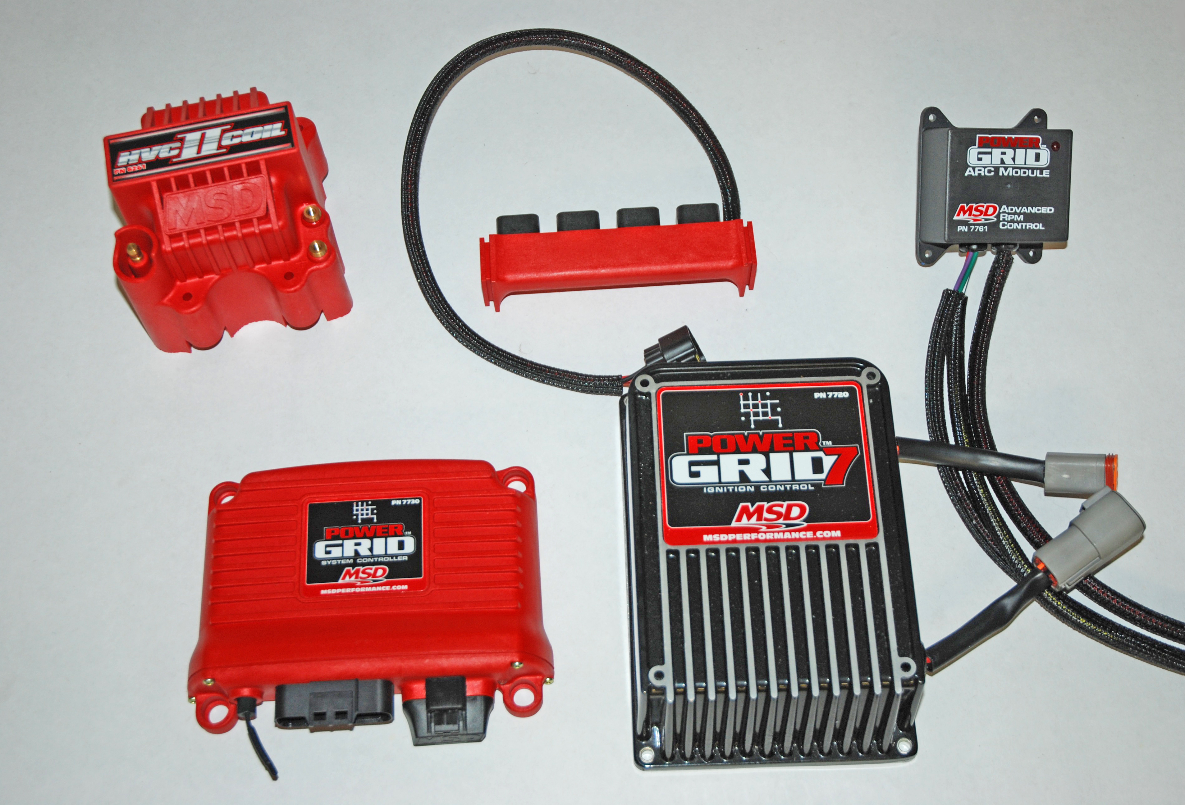
That’s not the end of it either. Using the most popular ignition systems on the market (MSD) as an example, many of their ignition systems make use of an electronic capacitor that is discharged through the ignition coil to fire the spark plugs. These capacitors can be charged in excess of 450 volts, and they can be charged far quicker than a coil. What this means is the coil becomes part of a much larger, much more sophisticated package of ignition components.
Another thing you’ll find today is that the layout and shape of coils has changed dramatically. Sure, the old canister coils are still around, but more and more coils are starting to look more like real transformers. And that’s really what they’re like inside too. With these newer style coils, less loss occurs during the transfer of electricity due to the closed core of the coil. If you look closely at a modern coil, you'll see the body is surrounded by a series of heat sinks. What's the reason for that? The idea is to remove heat generated by the coil. As you well know, today's modern ignition technology can create considerable amounts of energy, and that means heat is created in both the ignition box and the coil. Getting rid of the heat is important to both coil performance and life expectancy. That’s the reason for the heat sinks.
Another construction consideration of the transformer style coils is the “E-Core” or the “U-Core.” While earlier canister style coil configurations were built in a can of sorts, with a solid iron core in the very center and filled with oil (or sometimes epoxy), the newer transformer jobs have what is called a closed-core. In an E-Core coil, the actual shape of the core looks an “E” while a U-Core coil core obviously mimics a “U.” U-Core and E-Core transformer style coils have what is called a “closed magnetic path,” with the U-Core being the simplest to manufacture. In either case, a closed magnetic path means losses in inductance are minimized.
When purchasing a coil, don’t rush out and pick the largest, most powerful job available. Instead, it’s better to consult with your ignition parts manufacturer and use the correct coil for the application. There is no universally "correct" ignition coil. Instead, the coil should be matched precisely to the job.
Next issue, we’ll look at several of the more common coils used in MSD ignition applications. Watch for it.
Ignition coils aren’t really that complicated. Neither is the job they are tasked with. A coil functions a wee bit like a transformer. Its job is to create sufficient energy to jump the gap at the spark plug. It takes the 12 to 16 volts available from the battery power supply and, with the help of the ignition control box, it transforms that battery power into 10,000, 20,000, or even 40,000+ volts. Fair enough, but in a high performance or outright racing application it can become a little bit more complex.
Before we go any further, consider the makeup of a common coil. On the outside, coils typically have three posts that consist of a large secondary wire center tower that obviously leads to the distributor cap, along with a pair of threaded posts for the primary wire connections. These primary wire terminals are usually marked positive (+) or "Batt" and negative (-) or "Dist." While it is possible to reverse the polarity and get the engine started, coil output will be reduced considerably. Back to the coil: On the inside, the coil consists of an iron core. A long (long!) time ago, inventors discovered if they wrapped many wires around a piece of iron and powered those wires with electricity, a strong magnetic field was created. If they added another wrap or “coil” of wires near the first wrap or “coil” of wires, the magnetism created from the first coil induced current or voltage in the second coil of wires (even though they weren’t physically connected). That’s called “inductance.”
So what we have inside a coil is really two sets of wires wrapped around a core. The ratio of those "turns" of primary and secondary wire surrounding the core determines the amount of step-up power (between battery voltage and output voltage) the coil creates. Since the step-up from the relatively low 12 to 16 volts from the battery voltage to the output voltage of the voltage is high, the primary "turns" within the coil tend to be small, while the secondary "turns" tend to be much larger. What that means is if there are 70 turns of secondary compared to (for example) 1 turn of primary wire in the coil, then the “turn ratio” is 70. Given that info, wouldn’t it be better to simply buy a coil with the largest turn ratio? Not exactly. Sure, you can increase the voltage step-up by increasing the turns ratio, but it eventually becomes a case of diminishing returns. Keep adding turns and eventually the amount of secondary voltage will go down. Factor in the characteristics of the ignition system in use and you’ll find that picking the right coil is not simply a matter of adding turns to the coil.
There’s more, too; a coil with one form of turn ratio might make the engine easy to start. But once you get up to engine redline the coil won't function properly. Another coil winding ratio might be best suited for use at high engine rpm, but it won't work well to fire the spark when starting the engine. As a result of this, many coils tend to be a design of compromise.
When shopping for a coil, the most common way to describe a coil is by comparing secondary voltage. Does that mean the higher the secondary voltage the stronger the spark? Maybe not. The huge advertised voltage numbers of some coils on today’s market are simply theoretical. In the mindset of most people, bigger is usually better, especially when it comes to spark. In most cases, advertised coil secondary voltage figures are numbers obtained in a laboratory, but with no real loads placed upon the coil. In the real world, the 50,000, 60,000, and higher voltage figures may well be impossible to reach, simply because most of today's ignition components, such as distributor caps, rotors, and wires, are only capable of handling 35,000 to 45,000 volts. Even more compelling is the fact that current or amperage do much of the work in an ignition system, not the voltage. As a result, it’s best to not to evaluate the performance of a coil by high secondary voltage figures alone.
That’s not the end of it either. Using the most popular ignition systems on the market (MSD) as an example, many of their ignition systems make use of an electronic capacitor that is discharged through the ignition coil to fire the spark plugs. These capacitors can be charged in excess of 450 volts, and they can be charged far quicker than a coil. What this means is the coil becomes part of a much larger, much more sophisticated package of ignition components.
Another thing you’ll find today is that the layout and shape of coils has changed dramatically. Sure, the old canister coils are still around, but more and more coils are starting to look more like real transformers. And that’s really what they’re like inside too. With these newer style coils, less loss occurs during the transfer of electricity due to the closed core of the coil. If you look closely at a modern coil, you'll see the body is surrounded by a series of heat sinks. What's the reason for that? The idea is to remove heat generated by the coil. As you well know, today's modern ignition technology can create considerable amounts of energy, and that means heat is created in both the ignition box and the coil. Getting rid of the heat is important to both coil performance and life expectancy. That’s the reason for the heat sinks.
Another construction consideration of the transformer style coils is the “E-Core” or the “U-Core.” While earlier canister style coil configurations were built in a can of sorts, with a solid iron core in the very center and filled with oil (or sometimes epoxy), the newer transformer jobs have what is called a closed-core. In an E-Core coil, the actual shape of the core looks an “E” while a U-Core coil core obviously mimics a “U.” U-Core and E-Core transformer style coils have what is called a “closed magnetic path,” with the U-Core being the simplest to manufacture. In either case, a closed magnetic path means losses in inductance are minimized.
When purchasing a coil, don’t rush out and pick the largest, most powerful job available. Instead, it’s better to consult with your ignition parts manufacturer and use the correct coil for the application. There is no universally "correct" ignition coil. Instead, the coil should be matched precisely to the job.
Next issue, we’ll look at several of the more common coils used in MSD ignition applications. Watch for it.
This reminds me: if you are ever helping someone get an old, original car started, especially one with 6-volt ignition, and it doesn’t want to fire, check the battery installation. Older cars were “positive ground.” Yes, the positive side of the battery went to the frame and the negative to the starter, ignition, and accessories. If you are a modern guy, or even a late-middle-aged or old guy, the thinking is naturally negative ground. Reversing connection/polarity of the battery, the engine still turns over correctly, but the connections to the coil are effectively reversed and spark will be compromised to the point starting is unlikely. Cranking with a plug removed and laid on the block will show a fat, lazy, yellow spark instead of a crisp, blue, hot spark.
Thanks Jon. I’m an “old gear head” that has never heard about the positive ground in old cars…maybe that’s why my ’48 Ford spun it’s flathead V8 so slowly!
I was lucky to have someone even older than I watching my similar frustration. I really resisted believing him, it just seemed too odd compared to everything I “knew.”
So, we need 3 coils with two of them being activated by an RPM switch? 😉
One for starting the engine,
One for low to mid range RPMs,
And one for high RPMS….