


Why would you want to install a new K-member in your late model Mustang? The short and sweet reason is it makes a world of difference in how your car handles under load. Getting technical, most aftermarket k-members are made of tubular steel, which makes for a lighter yet stronger k-member that resists deflection under hard cornering loads than the stock parts do. Let’s take a look at what the Mustang k-member is, why you want to replace it, and how. Our example k-member will be the Maximum Motorsports Mm5KM-7.
What the K-Member Is and Why You Should Replace It
The k-member on your late model Mustang is basically just the front crossmember running under the engine. It contains the motor mounts and the control arm mounts. Straight from the factory, the stock unit is fine – it can stand up to the repeated stress of drag or road racing. However, they begin to weaken after repeated abuse.

If you look around some of the forums online, you’ll get mixed opinions – some say the factory k-member is the strongest and best you’ll get, while others say that aftermarket ones are better. My personal experience is that the right aftermarket k-member is going to be both lighter than the factory unit by up to 50 pounds, and is quite a bit stronger, especially when it comes to lateral stresses induced by road racing.
Having installed a few myself, my current favorite for late model (2005-2014) Mustangs, is the Mm5KM-7 from Maximum Motorsports (MM). Some of the others I’ve seen and that others have told me about make noticeable and negative changes to road noise, vibration, and harshness (NVH) felt, but the MM design doesn’t. The increased rigidity will improve your ‘Stang’s predictability and stability in the front end. This one also gives greater alignment adjustment, gives you more space in the engine compartment (for turbos!!), and allows for easier oil pan removal. Another reason I like the MM design is that it lengthens the wheelbase by 3/4 of an inch. This increases positive caster resulting in improved cornering ability.
What You Need to Install a New Late Model Mustang K-Member
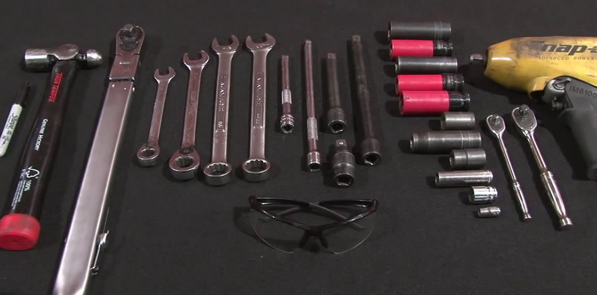
You’ll be removing and reinstalling several nuts and bolts during this install, so you’ll need a good assortment of wrenches and sockets, plus a ratchet and extensions. You’ll also need a floor jack and four jack stands. To finish up the installation once everything’s back in place, you’ll need a torque wrench. This isn’t one of those times when you can get away with just making sure the nuts and bolts are good and tight; you’ll need to torque some of them down.
You’ll also need something to support the engine. MM has an engine support brace but you can use a cherry picker or make your own engine support brace that braces off the strut towers. Finally, you’ll need a level surface like a garage to work on. Don’t try this on a driveway. You’ll need to do an alignment once the installation is complete. MM sells their Mm5TR-2 Bumpsteer adapter kit with their k-member kit as it’s required to keep your steering geometry correct. If your car already has them installed, you won’t need to buy the MM kit. Towards the end, you may also need the help of a buddy.
Step 1: Get the Car in the Air and Properly Supported

Firmly set the parking brake and raise the front end enough for you to comfortably slide under with extra space; you want the car at least 18 inches off the ground. Slide the jacks under the front rocker panel pinch welds and slowly lower the car onto the stands. Repeat at the rear of the car and remove the front wheels.
Step 2: Prep Up Top

If the car is equipped with electric power steering, disconnect the battery negative terminal, otherwise you can fry the rack control module. Using a 15 mm deep socket, remove the upper engine mount nut on each side of the car (two total). Properly and safely support the engine from above. It’s easiest to use some sort of support brace that’s braced off the strut towers and either a short chain bolted to the heads, or a ratchet strap wrapped under the oil pan. You can’t use a jack under the oil pan. At all.
Step 3: Remove Splitter and Crossmember Brace Bolts (2011-2014 Only)
There are eight bolts that secure the splitter to the underside of the car. These are seven mm bolts and can be removed either with a ratchet and socket or a nut driver. I prefer a 1/4 inch drive seven mm socket on my cordless drill.
Between the wheels, there are two bolts (one per side) and two nuts (one per side) that need to be removed. Up front, at the rear edge of the splitter are six bolts. All eight of these bolts need to be removed from the crossmember brace and are all 15 mm. The two front-most bolts are hidden by the rear edge of the splitter, so you’ll need to carefully pull it down to get at them.
Step 4: Disconnect the Tie Rods from the Knuckle/Spindle

The outer tie-rod ends need to be separated from the steering knuckle/spindle assembly next. There’s an 18 mm nut that needs to come off to do this. There may also be a cotter pin as a safety device to keep that nut from loosening. You may need to “convince” the tie-rod stud to separate from the knuckle with a few hammer smacks. In extreme cases, you’ll need a pickle fork. Remove the rod-end from the tapered stud if a bumpsteer kit has already been installed. Finally, using an 18 mm socket and 15 mm wrench, remove the ball joint pinch bolts from both sides.
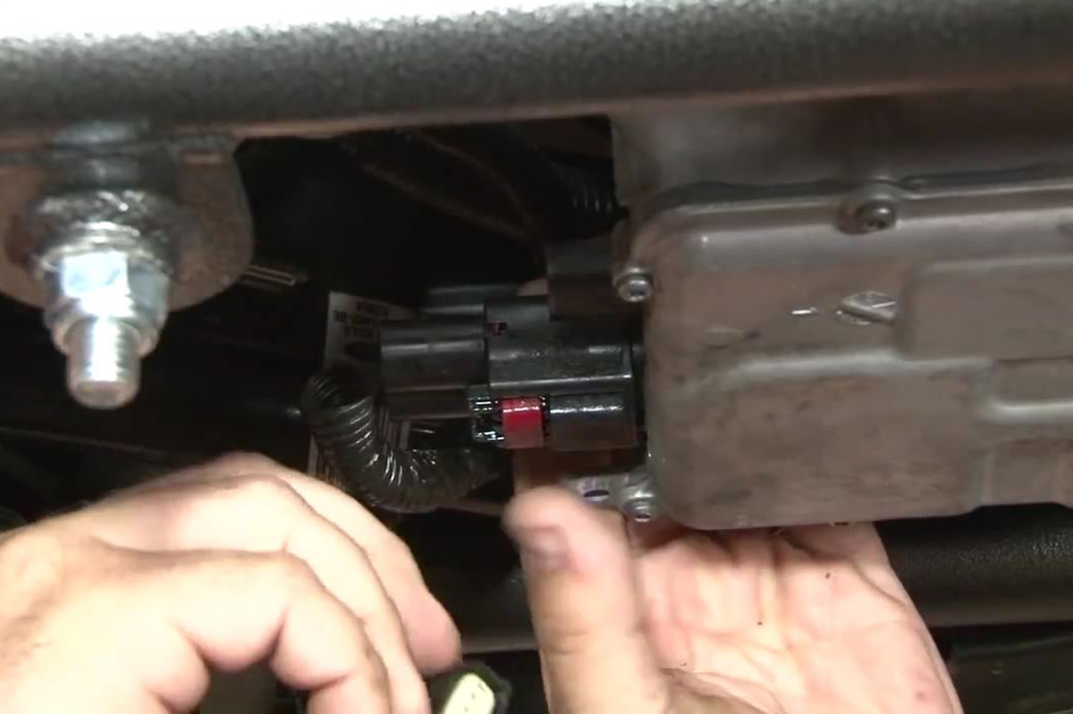
Step 5: Electric Racks Only: Disconnect the Steering Rack Wiring

On the driver side of electric steering racks are two electrical connectors that have to be disconnected. These connectors are double-locked. Each has a red tab that needs to be carefully slid away from the rack. Doing so allows you to release the secondary lock by pinching it and carefully pulling the connector away from the steering rack.
Step 6: Electric Racks Only: Finish Disconnecting the Steering Rack
On Mustangs equipped with electric steering racks, locate the steering rack control module. Next, locate the harness strain relief tab on forward, outboard corner of the module and disconnect it. Turn the key to the “On” position to unlock the steering wheel. Rotate the wheel.steering shaft until you can reach the 13 mm bolt that secures the u-joint to the input shaft. Remove the key from the ignition and remove the 13 mm bolt.
Step 7: Hydraulic Racks Only: Disconnect the Steering Rack

Locate and remove the bolt on the clamp securing the power steering hose to the center of the k-member. Unlock the steering column and rotate the input shaft until you can reach the u-joint retaining bolt. Lock the column and remove the 13 mm bolt.
Step 8: (All Cars) Remove the Frame Rail Bolts
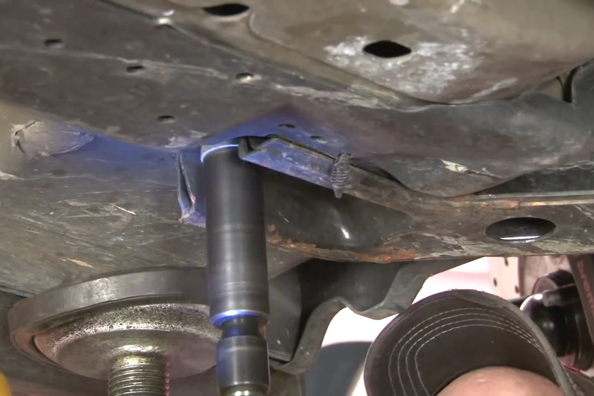
Locate the four lower frame rail bolts – two per side. Using an 18 mm socket, remove them. You may need to use a cheater bar or pipe on the ratchet as these bolts have Loctite threadlocker on them. Slide your jack under the k-member and firmly support the k-member without taking any of the weight of the car on the jack. Remove the four 18 mm upper frame rail bolts. Again, threadlocker was used at the factory, so you may need a cheater bar or pipe to break them loose if you don’t have an impact gun.

Step 9: Lower the K-Member

On vehicles equipped with electric racks, carefully lower the jack with the k-member on it. On cars equipped with hydraulic steering, be careful to not stress the power steering lines as you lower the jack just enough to remove the two (three on electric racks) 18 mm rack mounting bolts. You may need to wiggle the spindles to get the lower ball joints free. Use the zip ties that can with the kit to strap the rack to the sway bar for now..
Step 10: Remove the Motor Mounts and Control Arms from the Stock K-Member
There are four 13 mm bolts that secure the motor mounts to the stock k-member (two each) that need to be removed. The front control arms also have four bolts that secure them to the k-member. The two front bolts are 18 mm while the rear two will need to be removed using a 21 mm socket. If there are heat shields on the back side of the bushing shells on the control arms, remove and discard them.
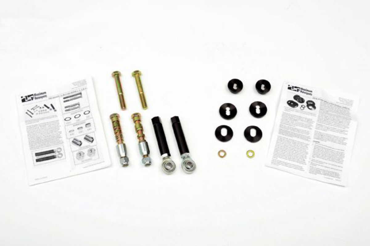
Step 11: Assemble the Aluminum Frame Rail Blocks
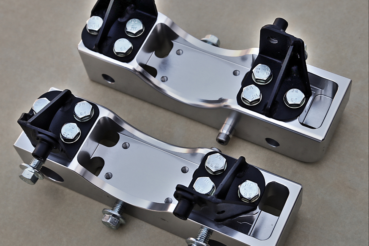
Locate the two eight mm socket head cap screws and the two alignment pins. Insert the screws into the pins and insert the pins into the holes on the top of the frame rail blocks. Torque these screws to 16 lb-ft. Place the blocks so the six threaded holes are facing you with the alignment pins facing up.
There are four engine mount brackets – two labeled number one and two labeled number two. Using six of the 10 mm X 25 mm bolts, with washers, attach the number one brackets to the right side of the aluminum blocks, with the welded nuts facing down after applying Blue threadlocker to the ends of the bolts. Using six more of the same bolts and washers, attach the number two brackets to the left side of the aluminum blocks after coating the threads with threadlocker. DON’T tighten any of these bolts yet.
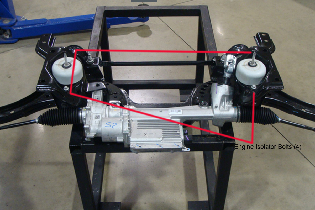
Install the engine isolators between the engine mount brackets with the bolt facing up like the alignment pins. Thread the factory mounting bolts through the mounts to the welded nuts on the mount adapters just enough to secure them. Torque the 10 mm bolts securing the brackets to the blocks to 30 lb-ft and then torque the isolator bolts to 41 lb-ft.
Step 12: Attach the K-Member Center Brace and Aluminum Frame Rail Blocks.
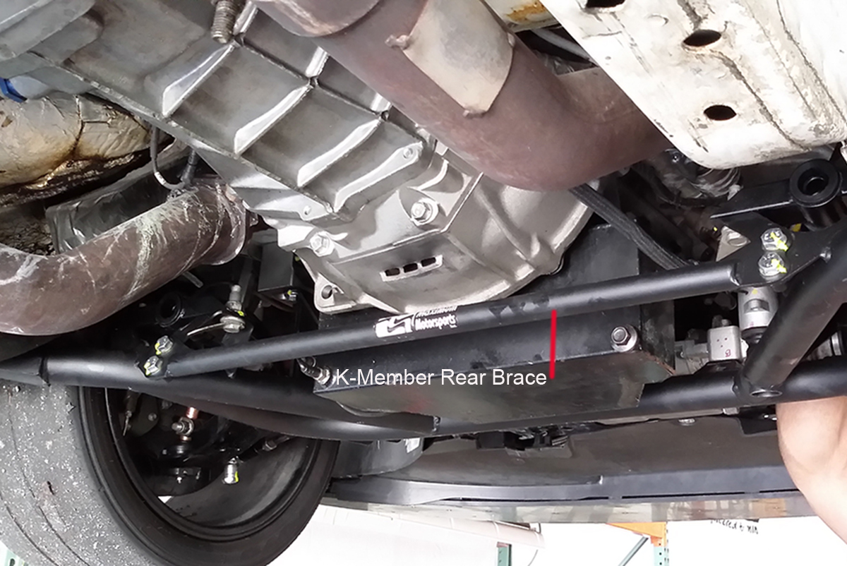
The k-member center brace is a bar that connects to the new k-member midway between the front and rear connects with two of the 10 mm X 25 mm bolts with a washer on each side. These should be torqued to 35 lb-ft. make sure the bottom of the k-member and the brace are flush.

Grab the six 12 mm X 35 mm bolts and coat the threads with Blue threadlocker. Place the assembled aluminum frame rails blocks on the k-member with the large radius facing towards the front and outboard of the k-member. Thread the bolts in, three to a side, leaving them loose enough that you can move the blocks around some.
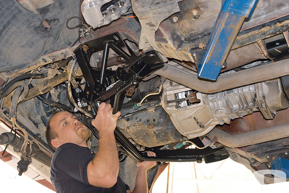
Step 13: Raise the Assembled K-Member into Place
Here’s where your buddy starts earning the beer you bribed him with. Lift the k-member into position. There are four bolts that protrude from the upper frame rails. These should slide into the aluminum frame rail blocks. You’ll probably need to wiggle the blocks back and forth to align the alignment pins into the locating hole and slot on the frame rails. (Hint: Slide the driver side into place first, then get the passenger side into position.) Make sure the studs on the engine isolators pass through their mounting holes on the engine.
Locate the eight 18 mm bolts you removed from the upper and lower frame rails and lightly coat them with Blue threadlocker. Loosely thread four of them back into place in the upper frame rails, two per side, leaving them just tight enough that you need to use a little effort to move the aluminum blocks back and forth. Now thread the four lower frame rails bolts in, again tightening them just enough that the aluminum blocks can still be moved.
Step 14: Align and Torque the K-Member in Place

Slide the lower control arms into the lower mounting holds on the new k-member. Pay attention, there are two. Only use the upper ones if you’re radically lowering the car. Find the lower control arm forward pivot mounting bolts you removed earlier and slide them into the lowest control arm mounting holes. Attach the rear pivot bushings to the new k-member using the factory hardware.
Loosely thread one of the 14 mm flanged nuts that came with the kit onto each of these bolts. Torque the rear pivot bushing mounting hardware to 136 lb-ft. Next, torque the front pivot bolts to 151 lb-ft. Note: You MUST torque the rear pivot bushings first. Otherwise you could end up with harmful preloading on the bushings.
Step 17: Reattach the Steering Rack
Clip the zip ties you used to hold the steering rack up and slide the rack into place. Make sure you get the steering input shaft and the u-joint couple properly. Locate the factory 12 mm bolts rack mount bolts and slide them through the rack housing into the mounting bosses on the k-member. Thread the two 12 mm-1.5 flange nuts that came with the kit onto these bolts and torque them to 85 lb-ft.
The kit came with a large flat washer. If your car has the electric rack, slide this washer over the 14 mm rack bolt and install them from the top of the rack and through the rack and k-member. Use the last 14 mm flange bolt and torque these to 85 lb-ft. If your car has hydraulic power steering, skip this.
Step 18: Finish Reinstalling the Rack
Reinstall the factory u-joint pinch bolt on the steering input shaft and torque it 18 lb-ft. If you’ve got electric power steering, reconnect the wiring connectors, making sure you double lock them by sliding the red tabs down toward the rack. Reinstall the strain relief tab on the control module.
Step 19: Reinstall the Lower Ball Joints to the Control Arms

Push down on the lower control arm and insert the ball joint into the spindle. There’s a chance you may need to loosen or remove the spindle to strut bolts, but you shouldn’t have to. Reinstall the spindle ball joint nuts and bolts and torque them to 73 lb-ft. If you’ve got hydraulic power steering, use the big worm gear clamp around the rack to secure the power steering hose relief bracket to the steering rack.
Step 20: Install the Bumpsteer Kit
Remove the old tie rod ends. Thread the bumpsteer adapter onto the end of the steering rack shaft. Insert the bumpsteer tie rod stud into the steering knuckle. Between the bottom of the stud and the new rod end, install the .48 inch, .24 inch, and .03 inch spacers and place the rod end on the stud. Place the remaining spacers on the bottom of the rod end assembly and thread and tighten the bolt.
Step 21: 2011-2014 Models: Replace the Splitter Bolts
Reinstall the eight splitter bolts you removed in Step 3. There is no specific torque for these. They just need to be tight,
Step 22: Lower the Engine into Place
Your engine will sit just a bit lower with the Maximum Motorsports k-member. This means that to finish up the install, you’ll need to carefully lower the engine over the isolator studs. Once you’ve done this, remove whatever you used to support the engine. Replace the two upper engine isolator bolts and torque them to 46 lb-ft.
Reinstall the front wheels and lug nuts. Get them as snug as you can. Carefully lower the rear of the car. Raise the front of the car off the stands and slowly lower and torque the wheels to factory specs. Now go get the alignment checked.
Now, Drive It Like Ya Stole It My Friends and Enjoy!
Leave a Reply