

![[Gallery] Okolona Street Rods Kentuckiana V Foundation Car Show](https://www.racingjunk.com/news/wp-content/uploads/2022/04/IMG_0774-e1650040587750-376x206.jpg)
![[Gallery] Road Rats Car Show](https://www.racingjunk.com/news/wp-content/uploads/2022/05/2A-e1651770667920-376x206.jpg)

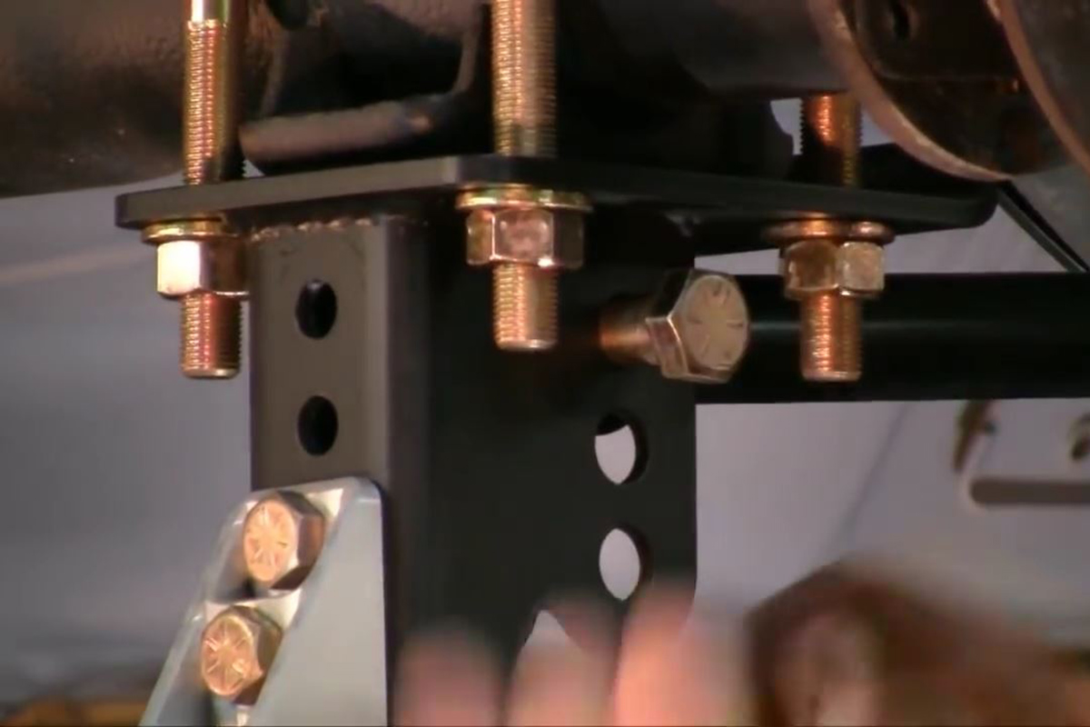
How to Install the 64-70 RideTech 4-Link
Click Here to Begin Slideshow
Up until the mid-70s to the mid-80s, leafspring rear suspensions were where it was at for muscle cars. Problem is, leafsprings have serious drawbacks. Stick a big, torquey motor under the hood with a strong transmission and, no matter how much money you put into the rear suspension, you’re still going to have the drawbacks of a leafsprung rear end.
All that engine and trans money was spent with one reason in mind: Getting down the track as quickly as possible. The problem is that leafsprings tend to want to unload when you tromp on the pedal at the light; they don’t want to allow every bit of torque being sent to your rear wheels to be transferred to the ground. They want to bend and induce wheel hop. You can almost completely eliminate wheel hop by removing those leafsprings and installing a quality 4-link rear end like Ridetech’s “Bolt-On” (some welding required) 4-Link kit. The major drawback of this kit is that you have to buy the Ridetech Shockwaves or coilovers separately.
Leave a Reply