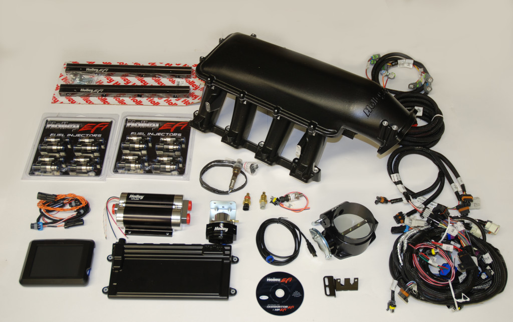
In the last few issues (Part I, Part II), we took a look at several of the “Hard Parts For Your Fuelie” (Holley’s hot new EFI system). Previously, we touched on Holley’s modular Hi-Ram intake and followed up with an article on Holley’s new billet throttle bodies. One critical part of the EFI hardware puzzle that many forget or gloss over is the actual wiring harnesses. And in a fuel-injected application, the harnesses are considerable and sophisticated. We’ll take a closer look at these wiring harnesses in this issue.
In the case of the Holley system, the harnesses were engineered from the beginning to be easy to install. While at first glance, the harness assemblies appear daunting, they’re actually clearly marked and in truth they’re essentially “plug and play” systems. By “clearly marked”, we mean that each of the connectors is labeled, basically telling you what they plug into. Depending upon the harness part number, there are several wires that are most likely not terminated. For example, on the main harness one non-terminated wire is the switched ignition power source wire (power when the engine is cranking). Others are listed in the ECU manual.
In the case of the 558-103 harness (LS2 Main Harness for Dominator & HP EFI systems) shown in the accompanying photos, direct-fit connections for stock style sensors include the following:
- Manifold Air Pressure
- Throttle Position Switch
- Coolant Temperature Sensor
- Crank Sensor
- Cam Sensor
- Stock Ignition Harness (Even/Odd)
- Idle Air Control
- Manifold Air Temperature
The harness also includes direct fit connectors for optional fuel pressure sensors, oil pressure sensors, and a wideband oxygen sensor.
Next up is the power harness. This is a simple harness with a non-terminated power lead and a ground lead. These go directly to the battery terminals. The main power ignition harnesses are designed for use with in concert with Holley EFI systems and they’re also plug and play arrangements. Like the main harness, the power harness is clearly marked.
Another harness you’ll need is for the wiring coils. Holley’s Number 558-309 kit is shown in the accompanying photos. This harness is used for Holley’s waste fire DIS coil package (four coils for eight cylinders). Like the other harness assemblies, they’re a straight plug and play arrangement. Here’s Holley’s info on wiring the coils:
(1) Connect the adapter harness marked “EVEN BANK” to the main harness coil connector marked “IGN EVEN”.
(2) Connect the adapter harness marked “ODD BANK” to the main harness coil marked “IGN ODD”.
(3) If the coils aren’t marked, mark them as “A”, “B”, “C”, and “D”.
(4) Plug the coil connectors on the “ODD BANK” harness into coils “A” and “C” as marked on the adapter harness.
(5) Plug the coil connectors on the “EVEN BANK” harness into coils “B” and “D” as marked on the adapter harness.
(6) The following is the spark plug connection order. Two cylinders are connected into each coil. It does not matter what cylinder is plugged into the twin coil tower connection.
Coil A – Cylinders 1 and 6 Coil B – Cylinders 5 and 8 Coil C – Cylinders 4 and 7 Coil D – Cylinders 2 and 3
Finally, the last plug and play harness is the Injector Harness. We’re showing Holley’s part number 558-201 in the photos. This harness connects the main harness to the fuel injectors (EV6 Style). You simply route the wires over the fuel rails, and plug the respective connector into the matching injector. Each of the wires is clearly marked, too, so it’s actually rather difficult to make a mistake!
We should also point out that Holley makes use of high-end OEM style connectors throughout. The harness assemblies are all nicely loomed and wrapped inside braided nylon style covers. Even for those who are “wiring challenged”, this is an easy system to hook up and it’s equally easy to route cleanly. For a closer look, check out the accompanying photos:


Leave a Reply